Do you have a question about the KeLi D2002E and is the answer not in the manual?
Explains load cell technology, components like A/D converters and microprocessors.
Describes indicator communication with load cells and its core functions.
Highlights key features: high precision, reliability, consistency, and anti-interference.
Lists load cell specs: data conversion, resolution, temperature coefficients, overload protection.
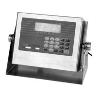
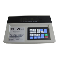
Outlines display terminal specs: performance, display range, units, and keyboard.
Explains connecting load cells to the indicator via a 9-pin connector.
Details the connection procedure for the printer using a 25-pin parallel interface.
Details PC connectivity via serial interface, including baud rates and data formats.
Instructions on selecting a load cell to view its internal statement number (ISN).
Explains how to display the ISN of a specific load cell and what it represents.
Step-by-step guide for manually adjusting corner calibration of load cells.
Outlines the process for performing automatic corner adjustment for improved accuracy.
Details initial calibration steps, including using the calibration plug.
Describes connecting load cells and powering on for indicator self-inspection.
Explains how to perform calibration and set parameters like division value and zero range.
Steps to turn on the indicator and select the operating mode for address modification.
Instructions for setting or changing the serial address of a load cell.
Explains the overall method for linearity adjustment, including using the calibration plug.
Details on entering the weight value for linearity revision.
Guide for installing platform and load cells, ensuring proper positioning and connection.
Steps to set the indicator coefficient and inspect corner-rectify coefficients.
Instructions for ensuring the platform is level and load cells share balanced force.
Covers power-on sequence, self-examination, and automatic zero setting.
Explains manual zero setting using the ZERO key.
Addresses no display/buzz issues, suggesting fuse or power checks.
Troubleshoots abnormal display/buzz, possibly due to unstable power or CPU issues.
Guides on resolving different corner readings, often related to balance base or sensor leveling.
Emphasizes importance of proper electrical grounding for safety.
Emphasizes disconnecting power before cleaning or maintenance.
| Type | Digital Multimeter |
|---|---|
| Diode Test | Yes |
| Continuity Test | Yes |
| Data Hold | Yes |
| Power Supply | 9V Battery |
| AC Voltage Range | 200V/600V |
| DC Current Range | 10A |
| Measurement Range | As per voltage, current, and resistance ranges |