Chapter 3 Installation & Connection
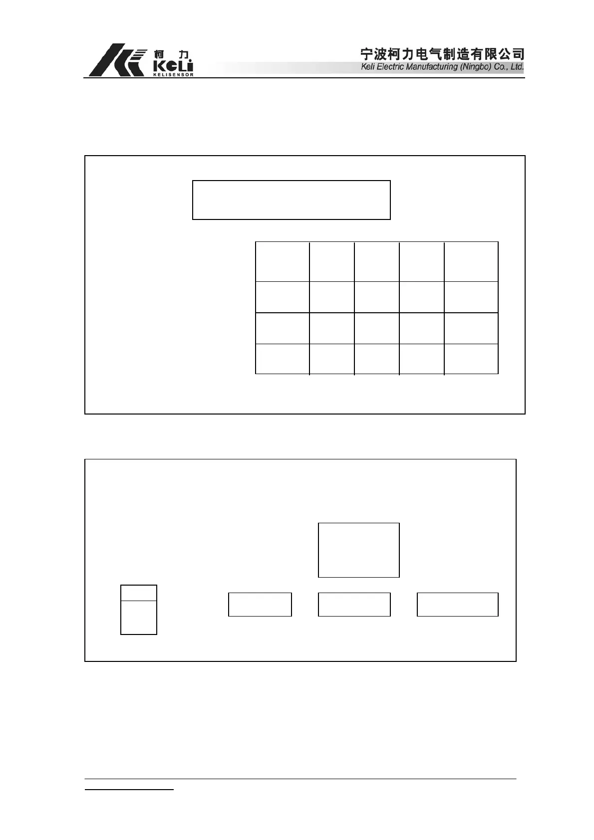
1. Front & Back view of Indicator
1 2 3
CARGO VEHICLE
CALIBRATION CHECK DATE
4 5 6
MEMORY PRINT FORM PRINT ENTER TIME
7 8 9
Preset Tare WEIGH Memory Tare
0
Amend Code ZERO ON/OFF
F1
Deduct Tare
Manua
Corner-Rectify
Linearity
Correction
Auto
Corner-rectify
Supplementary
Print
Unit:kg
AUTO DATE TIME CONST TARE ZERO
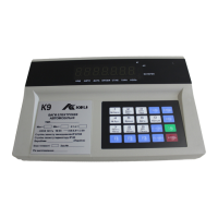
(Chart 2-1) Front view of Indicator
Fuse
Power Load cell input RS232 Print output
Calibration socket and display output
(Name plate)
(9 pins)
(15 pins)
(25 pins)
(Chart 2-2) Back View
2. Connection between Load cell and indicator
Load cell adopts 9 pins RS232 Terminal. Please refer to chart 2-3 for detailed
www.kelichina.com Page 8 of 38