Elektrischer Anschluss
Das Gerät ist entweder mit
einem Binder Stecker (8-Pol
Stecker) oder mit einem Kabelan-
schluss (Schraubklemme) aus-
gestattet:
Für beste Störfestigkeit empfeh-
len wir das Benutzen von abge-
schirmten Kabel mit beidseitig
angeschlossenem Schirm.
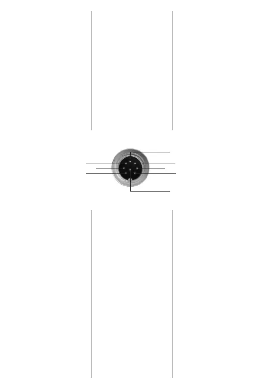
Steckerbelegung Binder 723,
8 Pol
Pin 1: +S1 (Relaiseingang)
Pin 2: -S1 (Relaisausgang)
Pin 3: +S2 (Relaiseingang)
Pin 4: +VCC (8…28 VDC)
Pin 5: RS 485 A
Pin 6: -S2 (Relaisausgang)
Pin 7: RS 485 B
Pin 8: GND
Schraubklemme:
Die Anschlüsse sind direkt auf
der Schraubklemme bezeichnet.
Electrical connection
The instrument is either equip-
ped with a Binder plug (8-pole
plug) or with a cable connection
(screw terminal):
For best immunity from inter-
ference we recommend to use
a screened cable, where the
shield is connected on both
ends.
Pin Assignment Binder 723,
8-pole
Pin 1: +S1 (Relay Input)
Pin 2: -S1 (Relay Output)
Pin 3: +S2 (Relay Input)
Pin 4: +VCC (8…28 VDC)
Pin 5: RS 485 A
Pin 6: -S2 (Relay Output)
Pin 7: RS 485 B
Pin 8: GND
Screw Terminal:
The connections are marked
directly on the screw terminal.
Raccordement electrique
L’instrument comporte soit un
connecteur Binder (connecteur
8 broches), soit un câble (bor-
nier).
Pour améliorer la protection
contre les influences parasites,
nous recommandons l’utilisation
de câbles blindés avec blindage
mis à la terre aux deux extrémi-
tés du câble.
Affectation des broches du con-
necteur Binder 723, 8 broches
1 : +S1 (entrée de relais)
2 : -S1 (sortie de relais)
3 : +S2 (entrée de relais)
4 : +VCC (8…28 VDC)
5 : RS 485 A
6 : -S2 (sortie de relais)
7 : RS 485 B
8 : GND
Bornier :
L’affectation de la borne figure
directement sur le bornier.
- 7 -
7 6
13
45
2
8
 Loading...