Interface (RS485)
L’interface RS485 permet de
communiquer avec le dV-2 PS.
Jusqu’à 128 appareils peu-
vent ainsi être interrogés par
le protocole de bus KELLER.
La description du protocole de
bus à utiliser pour l’écriture de
vos propres programmes ou
le logiciel PC d’affichage gra-
phique des valeurs de mesure
actuelles sont indiqués sur notre
site internet.
Configuration des seuils
via un PC
Les sorties d’état de seuil
peuvent également être confi-
gurées à l’aide du logiciel PC
«Pressure Switch Control». Les
manomètres doivent alors être
raccordés au PC par le conver-
tisseur d’interface K107 (RS232)
ou K104B (USB) de KELLER. Il
est également nécessaire de dis-
poser d’un câble adaptateur (op-
tion 5) pour les appareils pourvus
d’un connecteur Binder.
Interface (RS485)
The RS485 interface allows to
communicate with the dV-2 PS.
Up to 128 instruments can be
addressed via the KELLER BUS
protocol. The description of the
BUS protocol to write your own
software as well as the PC soft-
ware for graphical display of the
actual measuring values can be
found on our website.
Configuration of the Switch
Outpout with PC
The switching ouputs can also
be configured by using the
PC-Software „Pressure Switch
Console“. The instrument is con-
nected to the PC via the KEL-
LER interface converter K107
(RS232) or the K104B (USB).
Instruments equipped with a
Binder-plug require the adapter
cable „cable option 5“.
Schnittstelle (RS485)
Durch die RS485 Schnittstelle
kann mit dem dV-2 PS kommu-
niziert werden.
Bis zu 128 Geräte können über
das KELLER-Bus-Protokoll an-
gesprochen werden. Die Be-
schreibung des Bus-Protokolles
zum Erstellen eigener Software
sowie die PC-Software zum gra-
fischen Anzeigen aktueller Mess-
werte finden Sie auf unserer
Homepage.
Schaltausgangskonfiguration
mit PC
Die Schaltausgänge können
auch mit Hilfe der PC-Software
”Pressure Switch Console” kon-
figuriert werden. Das Gerät wird
über den Schnittstellenkonver-
ter K107 (RS232) oder K104B
(USB) von KELLER mit dem PC
verbunden.
Für Geräte mit Binder-Stecker
wird das Adapterkabel „Kabel-
option 5“ benötigt.
- 6 -
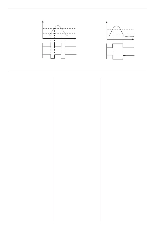
P/bar
P/bar
High
NO
NC
NC
t
t
1
0
1
0
0
1
0
1
Low
High
Low
NO
Fensterfunktion
Window Function
Fonction de fenêtre
Hysteresefunktion
Hysteresis Function
Fonction d’hystérési
Schaltausgang/
Schaltzustand
Switching output/
Switching status
Sortie de seuil/
État commuté
Schaltausgang/
Schaltzustand
Switching output/
Switching status
Sortie de seuil/
État commuté
 Loading...