24
Keller minimal windows
®
Keller minimal windows
®
4+ 06
Für diese Zeichnung behalten wir uns alle Rechte vo r, auch für den Fall der Patenterteilung, Gebrauchs- oder
Geschmacksmustereintragung. Ohne unsere schriftliche Zustimmung darf weder die Zeichnung selbst, noch
Vervielfältigung hiervon oder sonstige Wiedergaben des vol lständigen oder auszugsweisen Inhalts Dritten zugänglich
gemacht, oder in anderer Weise missbräuchlich verwendet werden.
This drawing is protected by copyright law. The a uthor reserves all rights, including all patent grants, registered utility
models and registered designs. The drawing is to be treated confidentially and may be used only by the person receiving
permission from the author and only for the purpose agreed on. Without the prior written consent of the author, neither
the drawing, nor copies of the drawing, nor other reproductions of the contents, in whole or in part, may be made
available to third parties or misused in any other way.
01
A4
KELL-15-0066
Status Änderungen Datum Name
Gezeichnet
Kontrolliert
Datum Name
08.07.2014
03.02.2015
B. Schumacher
W. Schulzen
Referenz:
Titel:
Zeichnungs-Nr.:
Maßstab:
1:2
MW Schiebeflügelpuffer
minimal windows
Material:
Schutzvermerk ISO 16016 beachten.
Refer to protection notice ISO 16016.
25-04-180
M
6
17,5
32,5
M
6
17,5
24
17,5
M
6
15
MW/MWP Schi ebefl ügelpuffer
MW/MWP sliding door bumper
ZK3
ZK2/G6/ST6/...
ZK1/G4/ST4/...
Position Bohrung Schiebeflügelpuff er
Position sliding door bumper drilling
17,5
101,5
M
6
ZK5
F
ür diese Zeichnung behalten wir uns alle Rechte vor, auch für den Fall der Patenterteilung, Gebrauchs- oder Geschmacksmustereintragung.
Ohne unsere schriftliche Zustimmung darf weder die Zeichnung selbst, noch Vervielfältigung hiervon oder sonstige Wiedergaben des
vollständigen oder auszugsweisen Inhalts Dritten zugänglich gemacht, oder in anderer Weise missbräuchlich verwendet werden.
This drawin
g is protected by copyright law. The author reserves all rights, including all patent grants, registered utility models and
registered designs. The drawing is to be treated confidentially and may be used only by the person receiving permission from the author and
only for the purpose agreed on. Without the prior written consent of the author, neither the drawing, nor copies of the drawing, nor o
ther
reproductions of the contents, in whole or in part, may be made available to third parties or misused in any other way.
01
A3
KELL-16-0012
Status Änderungen Datum Name
Gezeichnet
Kontrolliert
Datum Name
01.06.2012
06.07.2012
T. Franssen
W. Schulzen
Referenz:
Titel:
Zeichnungs-Nr.:
Maßstab:
1:4
Dichtstücke & Profile
Montage Abstreifer,
minimal windows 4+
Material:
Schutzvermerk ISO 16016 beachten.
Refer to protection notice ISO 16016.
Ansicht Griffprofil
View on handle bar
Ansicht Verhakungsprofil
View on junction profile
25-04-330
25-04-320
Griffprof il G4 (G3)
Handle bar G4 (G3)
Stulpprofil ST4 (ST3)
Double vent profile ST4 (ST3)
Verschraubung / screw connection
Dichtsatz (siehe Zeichnungen KELL-16-0013.01-10)
Sealing pack (see drawings KELL-16-0013.01-10)
Dichtsatz (siehe Zeichnungen KELL-16-0013.01-10)
Sealing pack (see drawings KELL-16-0013.01-10)
Gewindestifte mit Zapfen (DIN 915)
Set screw with pin (DIN 915)
26-00-100
F
üllplatte bei Griffprofil in Blendrahmen (2 Stück)
Fill plate a t handle bar in o uter frame (2 pie ces)
Füllplatte bei Verhakung in Blendrahmen 80mm
Fill plate at handle bar in outer frame 80mm
Montage Laufwagen, Abstreifer, Dichtstücke, Griffprofil und Verhakungsprofil - Schi ebeflügel
Installation of roller carriage, stripper, sealing pieces, handle bar and junction profile - Sliding leaf
02
Isolierstege bei BL, Griff & Stulp
aktualisiert
26.08.2019 TF
01
Art.-Nr. Laufwagen geändert
11.02.2015 BS
26-04-082 (Beispiel/Example)
26-04-130
16-04-160-0
M4x8
25-04-330
26-04-130
26-04-092 (Beispiel/Example)
02
02
02
02
A ( 1 : 1 )
A
F
ür diese Zeichnung behalten wir uns alle Rechte vor, auch für den Fall der Patenterteilung, Gebrauchs- oder Geschmacksmustereintragung.
Ohne unsere schriftliche Zustimmung darf weder die Zeichnung selbst, noch Vervielfältigung hiervon oder sonstige Wiedergaben des
vollständigen oder auszugsweisen Inhalts Dritten zugänglich gemacht, oder in anderer Weise missbräuchlich verwendet werden.
This drawin
g is protected by copyright law. The author reserves all rights, including all patent grants, registered utility models and
registered designs. The drawing is to be treated confidentially and may be used only by the person receiving permission from the author and
only for the purpose agreed on. Without the prior written consent of the author, neither the drawing, nor copies of the drawing, nor o
ther
reproductions of the contents, in whole or in part, may be made available to third parties or misused in any other way.
02
A3
KELL-16-0012
Status Änderungen Datum Name
Gezeichnet
Kontrolliert
Datum Name
01.06.2012
06.07.2012
T. Franssen
W. Schulzen
Referenz:
Titel:
Zeichnungs-Nr.:
Maßstab:
1:4
Dichtstücke & Profile
Montage Abstreifer,
minimal windows 4+
Material:
Schutzvermerk ISO 16016 beachten.
Refer to protection notice ISO 16016.
1
Gegenlaufverhakung auf das
U-Einfassprofil drehen
Turn counter direction junction
profile on U-profile
2
Verhakung in Höhe ausrichten
& Gewindestifte einschrauben
Place junction profile at t he
right height & screw in set screw
3
Einsatz auf U-Einfassprofil
und Verhakung drehen
Turn insert on U-profile
and junction profile
4
Einsatz festschrauben
Connect insert
M4x8
Gewindestift mit Zapfen
Set screw with pin
ST3,9x9,5
Senkkopfschraube
Countersunk screw
Montage Gegenlaufverhakung
Installation of counter dire ction junction profile
5
Abdeckung anbringe n
Install cover
70-7500K04003
Klemmschraube
Locking screw
03
03
Änderung Artikelnummer
17.01.2020 TF
02
Profil 16-04-260-0 & 16-04-262-0
abgeändert
22.04.2013 TF
01
Profil 16-04-260-0 & 16-04-262-0
hinzugefügt
18.01.2013 TF
On-site installation | 997-000120 | 07-2021
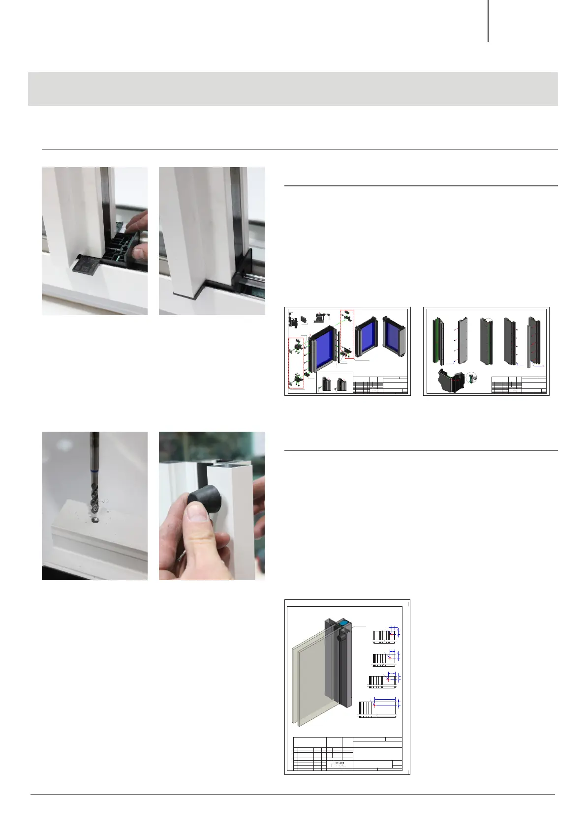
6. Insertion of the glazing
6.2 Sliding leaf installation
6.2.6
Remove the spacer, insert the sealing piece and screw it in
place.
See drawings:
KELL-16-0012.01
KELL-16-0012.02
6.2.7
Optional (for sliding-sliding-...-fix elements)
Cut thread and screw in sliding door bumper.
For exact position, refer to drawing:
KELL-15-0066.01
 Loading...