Kelly KLS-N Sinusoidal Brushless Permanent Magnet Motor Controller User’s Manual V2.9
3.2 Connections
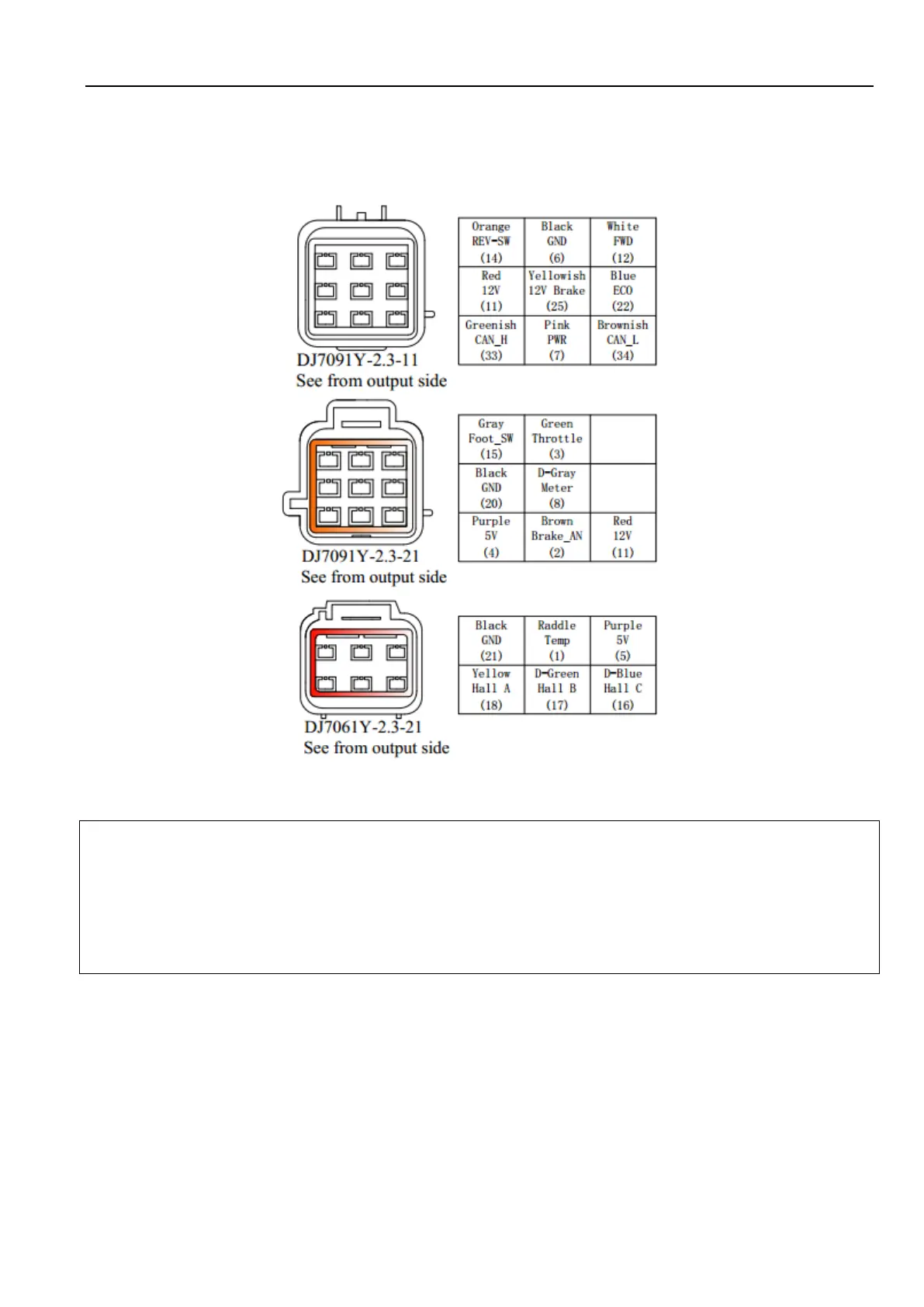
3.2.1 Pin definition of KLS-N Controller
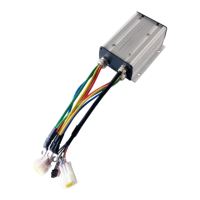
Figure 8: waterproof connector
1,The switch signal is valid to 12V
2,12V only can be used for LED or switch signals.
3,Boost and brake analog regen use the same port on pin2.
4, CAN bus is not included in KLS-N controller by default.
When boost is disabled in user program,pin2 is used as brake analog regen mode. When boost
is enable,pin2 is used for boost function. You may not use two functions at the same time.
DJ7091Y-2.3-11 Pin Definition
(14) REV_SW: Reverse switch input. Orange
(6) RTN: Signal return or power supply return. Black
(12) FWD: Forward switch or can be enabled as High speed switch function. White
(11) 12V:12V Source Red
(25) 12V brake switch. Yellowish
(22) ECO: Low speed switch function. Blue
 Loading...