Do you have a question about the Kelly KLS-N Series and is the answer not in the manual?
Introduces the Kelly sinusoidal wave brushless BLDC motor controllers' features, installation, and maintenance.
Details the various general functions and capabilities of the KLS-N controller.
Lists the key technical features and design aspects of the KLS-N controller.
Provides technical specifications such as operating frequency, current limits, and voltage ranges.
Explains the naming convention used for Kelly BLDC motor controllers, including model designations.
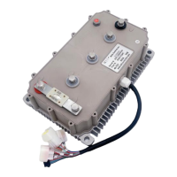
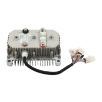
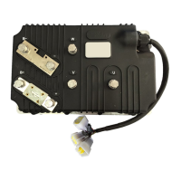
Describes how to properly mount the controller, emphasizing heat sinking and airflow for optimal performance.
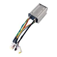
Provides a detailed breakdown of each pin on the KLS-N controller connectors.
Illustrates the standard electrical wiring diagram for connecting the KLS-N controller to a motor and battery.
Explains optional wiring configurations, such as for the secondary braking function.
Details the communication port for connecting the controller to a host computer for calibration and configuration.
Provides a step-by-step checklist to ensure proper installation and initial testing of the controller.
Details voltage limits, current settings, and identification angle for initial controller setup.
Covers parameters for motor nominal current, motor poles, and speed sensor types.
Focuses on parameters for regenerative braking, acceleration, and brake times.
Explains the essential procedure for performing the identification angle operation before motor use.
Provides instructions for periodic exterior cleaning of the controller, emphasizing safety precautions.
Explains how to configure the controller using RS232 or USB ports with a host computer or Android APP.
Lists and explains various error codes generated by the controller, their causes, and solutions.
| Brand | Kelly |
|---|---|
| Model | KLS-N Series |
| Category | Controller |
| Language | English |