Do you have a question about the Kelly KLS7230S and is the answer not in the manual?
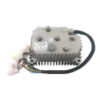
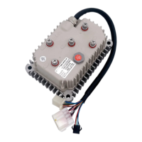
Introduces Kelly Small sinusoidal wave BLDC motor controllers, their features, installation, and maintenance.
Lists extended fault detection, battery monitoring, current control, temperature protection, configuration options, and various input signals.
Details features like microprocessor intelligence, efficiency, reversing, voltage monitoring, current sensing, protection, housing, and optional functions.
Lists electrical specifications like operation frequency, standby current, sensor supply current, and voltage ranges.
Explains the naming convention for Kelly BLDC motor controllers and provides a table of models with their specs.
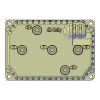
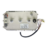
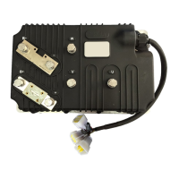
Provides guidelines for mounting the controller, emphasizing clean, dry conditions and proper heat sinking for optimal performance.
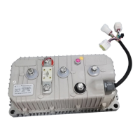
Details the pin definitions for the waterproof connectors used on the KLS-S controller.
Covers standard and optional wiring diagrams for the KLS-S controller, including diagrams for different connector types.
Outlines the checkout procedure before operating the vehicle, referencing LED codes and essential checks.
Covers parameter settings for low and over voltage protection, current limits, and identification angle.
Details parameters for motor nominal current, poles, speed sensor type, and resolver poles.
Explains parameters related to braking, acceleration time, and PID adjustments for motor control.
Guides users on performing the identification angle operation for KLS controllers using PC or Android software.
Provides instructions for periodic exterior cleaning of the controller, emphasizing safety precautions.
Explains how to configure the controller using a host computer via RS232 or USB, including software requirements.
| Continuous Current | 30A |
|---|---|
| Peak Current | 80A |
| Power Rating | 1.8kW |
| Efficiency | >90% |
| Protection Features | Over-voltage, Under-voltage, Over-current, Over-temperature, Short-circuit |