Do you have a question about the Kelly KLS7218N and is the answer not in the manual?
Introduces KLS-N controllers, features, installation, and maintenance.
Details various operational functions like fault detection, voltage monitoring, and protection features.
Lists key technical features such as microprocessor intelligence, rectification, and protection mechanisms.
Lists technical specifications like operation frequency, current, and voltage ranges.
Explains the naming convention for Kelly BLDC motor controllers.
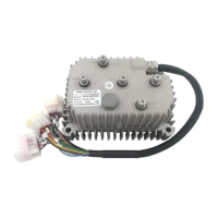
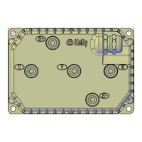
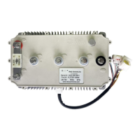
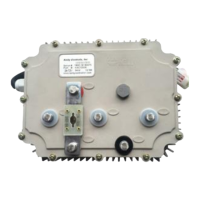
Provides instructions on how to mount the controller for optimal performance and heat dissipation.
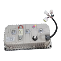
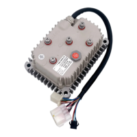
Details the various connection points and their functions on the KLS-N controller.
Explains the pin assignments for the controller's connectors.
Illustrates the standard wiring diagram for connecting the KLS-N controller.
Describes optional wiring configurations, specifically for brake switch functionality.
Details the communication port for connecting to a host computer.
Provides a checklist to ensure proper installation before operating the vehicle.
Covers initial parameter settings like low/over voltage limits and current percentage.
Focuses on motor identification parameters like nominal current and pole count.
Details parameters for acceleration, braking, and regen time settings.
Guides users on performing the critical motor identification process.
Provides instructions for the exterior cleaning of the controller.
Explains how to configure the controller using PC software or Android App.
| Brand | Kelly |
|---|---|
| Model | KLS7218N |
| Category | Controller |
| Language | English |