Do you have a question about the Kelly KLS7218S and is the answer not in the manual?
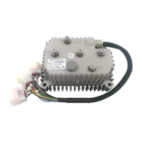
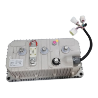
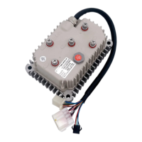
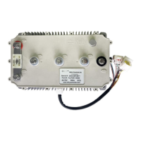
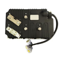
Introduces Kelly Small sinusoidal wave BLDC motor controllers, their features, installation, and maintenance.
Lists various functions like fault detection, voltage monitoring, current control, and connection types.
Details features such as microprocessor intelligence, synchronous rectification, electronic reversing, and protection mechanisms.
Outlines technical specifications like operation frequency, supply voltage, current limits, and temperature ranges.
Explains the naming convention for Kelly BLDC motor controllers and lists supported models.
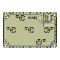
Provides guidelines for controller mounting, including surface preparation and thermal considerations.
Details pin definitions, standard wiring diagrams, optional wiring, and communication ports for the controller.
Provides a step-by-step checkout procedure before operating the vehicle.
Covers initial parameter settings like Low Volt, Over Volt, Current Percent, Battery Limit, and Identification Angle.
Focuses on motor identification parameters like Nominal Current, Motor Poles, and Speed Sensor Type.
Details braking parameters like RLS TPS Brk %, NTL Brk %, Accel Time, and Brake Time.
Explains the process of performing identification angle operation for motor setup and configuration.
Provides instructions for the exterior cleaning of the controller.
Explains how to configure the controller using a host computer via RS232 or USB.
| Operating Frequency | 16kHz |
|---|---|
| Standby Battery Current | < 0.5mA |
| Throttle Input | 0-5V |
| Cooling Method | Natural Cooling |
| Continuous Current | 50A |
| Protection Features | Over-voltage, Under-voltage, Over-current, Over-temperature |