Kelly KLS-N Sinusoidal Brushless Permanent Magnet Motor Controller User’s Manual V2.9
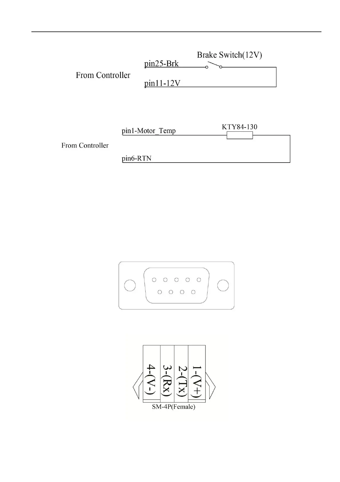
Figure 11: Wiring of brake switch(12V): 12V is provided by KLS-N controller on pin11
Figure 12: Wiring diagram for motor temperature sensor
NOTE: KLS controller can support KTY84-130/150 and KTY83-122 thermistors.
3.2.4 Communication Port
A 4pin connector to RS232 port is provided to communicate with host computer for calibration and
configuration.
Figure 13: RS232 Interface on 4pin connector to RS232 converter
Figure 14:SM-4P connector for communication interface on KLS-N controller
 Loading...