EasyManua.ls Logo

Kemppi 450 User Manual

Kemppi 450
28 pages
To Next Page IconTo Next Page
Page #1 background imageLoading...
Page #1 background image
Operating manual • English
Käyttöohje • Suomi
Bruksanvisning • Svenska
Bruksanvisning • Norsk
Brugsanvisning • Dansk
Gebrauchsanweisung • Deutsch
Gebruiksaanwijzing • Nederlands
Manuel d’utilisation • Français
Manual de instrucciones • Español
Instrukcja obsługi • Polski
Инструкции по эксплуатации • По-русски
操作手册中文
Manual de utilização • Português
Manuale di istruzioni • Italiano
EN
FI
SV
NO
DA
DE
NL
FR
ES
PL
RU
ZH
PT
IT
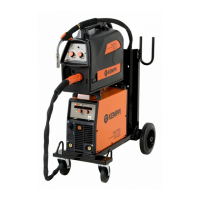
FastMig Pulse
350, 450
CHANNEL
MENU
P65

Questions and Answers:

Kemppi 450 Specifications

General IconGeneral
Welding processMIG/MAG
Wire sizes (Fe solid)1.6 mm
Wire sizes (Fe cored)1.6 mm
Wire sizes (Al)1.6 mm
Operating temperature range+40 °C
Protection classIP23
StandardsIEC 60974-1, IEC 60974-10

Summary

INTRODUCTION

1.1 GENERAL

General information about the welding equipment and manual.

1.2 ABOUT FASTMIG PULSE PRODUCTS

Details on FastMig Pulse 350 and 450 welding power sources.

INSTALLATION

2.1 BEFORE USE

Checks and precautions before operating the welding machine.

2.2 DISTRIBUTION NETWORK

Information on connecting to the electrical distribution network.

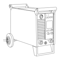
2.3 MACHINE INTRODUCTION

Overview of the machine components and their functions.

2.4 POSITIONING OF THE MACHINE

Guidelines for correctly positioning the welding machine.

2.5 CONNECTING CABLES

Information on various cable connections for the welding system.

2.5.1 WATER COOLED SYSTEM CONNECTIONS

Diagram and description for water-cooled system connections.

2.5.2 GAS COOLED SYSTEM CONNECTIONS

Diagram and description for gas-cooled system connections.

2.5.3 CONNECTING TO MAINS POWER

Instructions on how to connect the machine to the mains power supply.

2.5.4 WELDING AND EARTH RETURN CABLES

Recommendations for selecting and using welding and earth return cables.

2.5.5 INTERCONNECTION WITH WIRE FEEDER

Information on connecting the wire feeder unit to the power source.

OPERATION CONTROL

3.1 MAIN SWITCH AND PILOT LAMPS

Operation of the main switch and explanation of pilot lamps.

3.3 COOLING FAN AND MMA WELDING

Details on cooling fan operation and manual metal arc welding.

USING THE MACHINE

4.1 ARC WIZARD P65 LAYOUT

Overview and layout of the Arc Wizard P65 setup panel interface.

4.2 SETUP PANEL P65 QUICK GUIDE

A quick guide to operating and setting up the P65 panel.

4.3 WELDING PARAMETERS AND FUNCTIONS

Details on welding parameters and their functions.

4.3.1 MIG WELDING PARAMETERS

Details on MIG welding parameters like WFSpeed, Voltage, Dynamics.

4.3.1 1-MIG, PULSE MIG, DOUBLE PULSE MIG PARAMETERS

Parameters for 1-MIG, Pulse MIG, and Double Pulse MIG welding.

4.3.1 WISEROOT/WISETHIN AND MMA PARAMETERS

Parameters for WISEROOT/WISETHIN and MMA welding processes.

4.3.2 WELDING FUNCTIONS OVERVIEW

Explanation of various welding functions like 2T/4T, HotStart, CraterFill.

4.3.2 WELDING FUNCTIONS DETAILS

Details on CraterTime, timers, creep start, start power, and WISEROOT functions.

4.3.2 ADVANCED FUNCTIONS AND SYSTEM CONFIG

Advanced functions and system configuration settings.

4.3.2 CONTROL AND TIMING FUNCTIONS

Settings for weld data, display, gas timing, and controls.

4.3.2 ADMINISTRATOR MENU AND BUTTON FUNCTIONS

Administrator menu, PIN code, and button functions explained.

4.3.3 WELDING SOFTWARE DELIVERY PROFILE

Information on available welding software and delivery profiles.

GETTING STARTED

FIRST LANGUAGE SELECTION

Instructions for selecting the operating language of the interface.

NEW CHANNEL JOB NUMBER CREATION

How to create and manage new welding channels (jobs).

EDITING EXISTING CHANNEL JOB NUMBERS

Steps to edit existing welding channels (jobs).

EDITING CHANNEL JOB NUMBERS (CONTINUED)

Detailed steps for editing welding channels, including gas and curve selection.

MEMORY JOB CHANNELS AND USER CHANNELS

Explanation of memory job channels and user channel management.

P65 FAST FUNCTION KEYS

Description of the fast function keys (F1, F2, F3) on the P65 panel.

BASIC TROUBLESHOOTING

OPERATION DISTURBANCES

6.1 OVERLOAD PROTECTION OPERATION

Explanation of the thermal protection lamp and its operation.

6.2 CONTROL FUSES

Information about the control fuse and its purpose.

6.3 MAINS SUPPLY VOLTAGE AND PHASE ISSUES

How mains voltage variations and phase loss affect machine operation.

MAINTENANCE

7.1 DAILY MAINTENANCE

Recommended daily checks and cleaning procedures for the machine.

7.2 PERIOD MAINTENANCE

Periodic maintenance tasks, including cleaning and checks.

7.3 SERVICE SHOP MAINTENANCE

Maintenance tasks performed by authorized service workshops.

DISPOSAL OF THE MACHINE

ORDERING NUMBERS

TECHNICAL DATA

Related product manuals