Do you have a question about the Kenmore 795.71303.010 and is the answer not in the manual?
Important safety and preparation steps before servicing the appliance.
Detailed electrical ratings and consumption data for the refrigerator.
Performance data under specific ambient temperature conditions without load.
Procedures for removing refrigerator doors.
Detailed role, composition, and usage notes for the compressor.
Composition, role, and usage notes for the PTC starter.
Definition, role, and construction of the overload protector.
Diagnostic steps for compressor and electrical components.
Troubleshooting steps for the PTC starter and overload protector.
Troubleshooting for other electrical parts affecting cooling.
A chart to diagnose refrigerator complaints based on symptoms.
Diagnostic flowchart for sealed system problems.
Detailed explanation of icemaker modes and operations.
Detailed description of the Printed Circuit Board (PCB) functions.
Circuit diagram and voltage checks for the power supply.
Explanation of temperature sensor circuits and voltage readings.
Resistance values for temperature sensors at various temperatures.
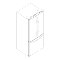
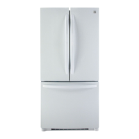
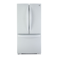
| Style | French Door |
|---|---|
| Color | Stainless Steel |
| Number of Doors | 3 |
| Total Capacity | 28.5 Cu. Ft. |
| Refrigerator Capacity | 15.7 Cu. Ft. |
| Freezer Capacity | 6.9 Cu. Ft. |
| Number of Refrigerator Shelves | 2 Fixed |
| Number of Refrigerator Bins | 5 |
| Humidity Controlled Crispers | - |
| Number of Freezer Shelves/Baskets | 2 |
| Refrigerator Temperature | 33°F to 41°F |
| (-14°C) | - |
| Refrigerator Special Features | Night Mode |
| Freezer Special Features | DuraBase Solid Drawer Base |
| Defrost System | Frost-free (Automatic) |
| Noise level | - |
| Refrigerant | R134a |
| Energy Class | - |
| Annual Energy Consumption | 466 kWh |
| Voltage | - |
| Frequency | 60 Hz |
| Current | - |
| Depth | 28 1/4 in |
|---|---|
| Height | 70 1/4 in |
| Width | 36 in |
| Net Weight | 331 lbs |