Do you have a question about the Kenmore 795.78773.801 and is the answer not in the manual?
Safety and preparation guidelines before servicing the unit.
Details on voltage, current, resistance, and energy consumption.
Performance metrics under no-load conditions.
Key parameters of the refrigeration system, including capacity and pressure.
List of common replacement parts with their part numbers.
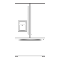
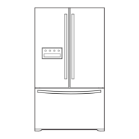
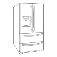
Physical dimensions of the refrigerator for installation and clearance.
Step-by-step instructions for removing and replacing refrigerator doors.
Procedure for removing and replacing the evaporator fan and motor.
Guide for accessing and replacing the defrost control assembly.
Instructions for removing and replacing the main printed circuit board.
Steps for disassembling and accessing the refrigerator dispenser unit.
Procedure for removing and replacing the ice maker assembly.
Detailed steps for removing and reinstalling the freezer pullout drawer.
Method for disassembling the water valve assembly.
Information on the compressor's role, composition, and usage notes.
Details on the TSD starter, its function, and application in refrigeration systems.
A table listing error codes, detection categories, and generation factors.
Guides for diagnosing and resolving specific error codes like sensor or fan failures.
Steps for diagnosing issues with specific modes like CUBE, Crush, Water, and LED functions.
Explanation of the ice maker's operational cycle and states.
Details on the ice maker's modes including Icemaking, Harvest, and Fill/Park.
Procedure for conducting forced tests on the ice maker functions.
Information on ice maker error codes and their meanings.
How to test the fuse-M and sensor within the defrost controller assembly.
Method for testing the resistance of the defrost sheath heater.
Procedure for testing the freezer and refrigerator door switches using a multimeter.
Testing method for the dispenser solenoid resistance.
Testing procedures for the geared motor and cube solenoid.
How to test the resistance of the refrigerator compartment damper.
Explanation of various user interface functions like temperature control, ice selection, and lights.
Guide on how to enter and use the PCB test modes for diagnostics.
Details on the power circuit and various PCB functions like fan and sensor controls.
Visual representation and part numbers for the main PWB.
Exploded view and part numbers for exterior and structural components.
Exploded view and part numbers for freezer compartment components.
Exploded view and part numbers for refrigerator compartment components.
Exploded view and part numbers for refrigerator and freezer doors.
Exploded view and part numbers for ice maker and ice bank components.
| Brand | Kenmore |
|---|---|
| Model Number | 795.78773.801 |
| Type | French Door |
| Ice Maker | Yes |
| Water Dispenser | Yes |
| Finish/Color | Stainless Steel |
| Dimensions/Width | 35.75 inches |
| Dimensions/Height | 69.875 inches |
| Energy Star Certified | Yes |