Do you have a question about the Kenmore 795.78753800 and is the answer not in the manual?
Instructions for safely disconnecting power before service.
Electrical ratings and power consumption details.
List of available replacement parts for the appliance.
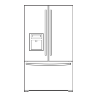
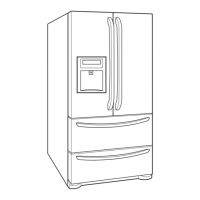
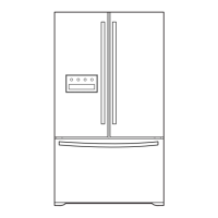
Diagram showing and listing key refrigerator components.
Step-by-step guide for removing and replacing refrigerator doors.
Procedures for door gasket removal and replacement.
Steps to adjust and align refrigerator doors properly.
Instructions for removing and replacing the evaporator fan motor.
Procedure for replacing the defrost control assembly.
Guide for replacing refrigerator compartment and freezer lamps.
Procedure for replacing the main printed circuit board (PWB).
Procedure for removing and replacing the icemaker assembly.
Detailed steps for removing and reinstalling the pullout drawer.
Procedure for disassembling the water valve.
Steps for separating and installing the pull out drawer.
Role, composition, and usage notes for the compressor.
Composition, role, and usage notes for the PTC starter.
Definition, role, and cross-section of the overload protector.
Circuit diagrams for Main, Dispenser, and Display PWBs.
Troubleshooting steps for compressor and electrical issues.
Troubleshooting for other electrical components like fan motors.
Chart to diagnose issues based on complaints.
Diagnostic flowchart for sealed system issues.
Overview of the icemaker's operation principle.
Detailed explanation of icemaker functions: Icemaking, Harvest, Fill/Park.
Explanation of error codes for the ice maker.
Overview of MICOM control functions, display, and indicators.
How to activate and use the Ultra Ice function for rapid freezing.
Detailed explanation of Ultra Ice function timing and operation.
Explanation of the door alarm and buzzer functionality.
Explanation of the automatic defrosting cycle.
Information on automatic diagnosis and error codes.
Guide to using the product's test mode for diagnostics.
Information on Printed Circuit Board (PCB) functions and circuits.
Diagram and explanation of the power supply circuit for the PCB.
Circuit for load, fan, and door detection.
Diagram and explanation of the temperature sensor circuit.
Sensor resistance specifications across various temperatures.
Circuit for the stepping motor controlling the compartment damper.
Circuit diagram for the dispenser drive system.
Explanation of LED indicators in refrigerator/freezer compartments.
General troubleshooting guide for common issues.
Diagram and parts list for the main PCB.
Diagram of the dispenser drive PCB assembly.
| Brand | Kenmore |
|---|---|
| Model | 795.78753800 |
| Category | Refrigerator |
| Language | English |