Do you have a question about the Kenmore 795.78752.801 and is the answer not in the manual?
Instructions to disconnect power before performing any service on the appliance.
Information intended for individuals with electrical, electronic, and mechanical experience.
Details on voltage, current, leakage, and energy consumption of the refrigerator.
Performance data for refrigerator and freezer compartments at different ambient temperatures.
Information on compressor capacity, vacuum, pressure, refrigerant type, and compressor BTU.
Required clearances at the top, sides, and rear for proper air circulation.
List of various replacement parts with their corresponding part numbers.
Diagram illustrating the air circulation path within the refrigerator.
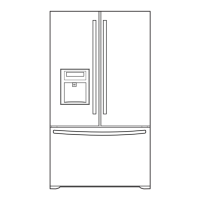
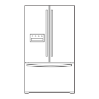
Detailed measurements including depth, height, and width of the refrigerator.
Critical safety warnings including explosion hazards and electrical shock precautions.
Step-by-step instructions for removing and reinstalling the refrigerator doors.
Procedures for removing and replacing the refrigerator door gasket.
Instructions for adjusting refrigerator doors to ensure proper alignment and sealing.
Steps for removing and replacing the evaporator fan motor assembly.
Procedure for replacing the ice fan scroll assembly.
Details on the defrost sensor and fuse-M, and how to replace the assembly.
Instructions for replacing the refrigerator and freezer compartment lamps.
Steps to remove and disconnect the multi duct assembly.
Procedure for removing and replacing the main Printed Wiring Board (PWB).
Steps for disconnecting the funnel and button assembly for dispenser service.
Procedure for removing and replacing the display PWB.
Steps for removing and replacing the dispenser funnel.
Instructions for removing and replacing the sub PWB for the dispenser.
Procedure for removing and replacing the duct door.
Steps for removing and replacing the ice corner door.
Procedure for removing and replacing the icemaker assembly.
Instructions for removing the auger motor cover and disconnecting the wire harness.
Steps for gripping and removing the door ice bin.
Procedure for inserting the door ice bin, avoiding contact with the icemaker.
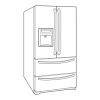
Detailed steps for removing and reinstalling the pullout drawer assembly.
Steps for correctly reinstalling the pullout drawer components and assembly.
Procedure for turning off water and disassembling the water valve.
Steps for loosening screws and disassembling the fan assembly and motor.
Instructions for separating and installing the pull out drawer using hooks and gears.
Explanation of the compressor's function, composition, and handling precautions.
Details on the PTC starter's composition, role, and important usage notes.
Definition, role, and adjustment precautions for the Overload Protector.
Steps for removing the PTC cover, including disconnecting and loosening screws.
Flowchart for diagnosing issues with the compressor and related electrical components.
Diagnosis charts for issues with fan motors, defrosting, and sensors.
Table linking specific complaints to points to check and recommended remedies.
Troubleshooting chart based on refrigeration cycle states and potential causes like leakage or clogs.
Diagnostic flowchart for 'Not Cooling' complaints related to the sealed system.
Flowchart detailing the icemaker's operational cycle from power on to test mode.
Explanation of Icemaking, Harvest, and Fill/Park modes with water supply details.
Procedure for performing a forced operation test on the icemaker.
Error codes and their meanings for the icemaker water supply control panel.
Basic functions of the refrigerator and freezer temperature control.
Instructions to switch the display between Fahrenheit (°F) and Celsius (°C).
How to lock and unlock the dispenser and display buttons for safety or child lock.
Explanation of the water filter replacement indicator light and reset procedure.
How to select and use the Ultra Ice function for quick freezing.
Instructions for selecting water, crushed ice, or ice cubes from the dispenser.
Description of the dispenser light's normal, auto, and ON status modes.
Details on freezer fan motor speeds (high/standard) and their usage conditions.
How the cooling fan motor operates in conjunction with the compressor and its speeds.
Explanation of the icing fan control via sensor and failure sensing methods.
Purpose, activation, and operation parameters of the Ultra Ice function.
Description of the audible alarm that sounds when a door is left open.
Details on when defrosting starts, stops, and potential malfunctions.
Overview of the automatic diagnosis system and how defect codes are displayed.
Table of error codes, generation factors, and remarks for the icemaker.
Procedure for entering and operating the test mode for PCB and function checks.
PCB functions, including the power circuit schematic and voltage outputs.
Circuit checks and voltage outputs for load, fan, and door detection.
Circuit diagram and status checks for various temperature sensors.
Circuit description for the reversible DC motor used to open/close the damper.
Circuit details and voltage outputs for the dispenser drive system.
Circuit details and output voltage for the LED module in the refrigerator/freezer room.
Troubleshooting common issues like power, cooling, and temperature problems.
A detailed diagram of the main Printed Wiring Board (PWB) layout.
A diagram showing the components and layout of the dispenser drive PWB.
| Brand | Kenmore |
|---|---|
| Model Number | 795.78752.801 |
| Category | Refrigerator |
| Type | French Door |
| Ice Maker | Yes |
| Water Dispenser | Yes |
| Finish / Color | Stainless Steel |
| Width | 35.75 inches |
| Energy Star Certified | Yes |
| Depth | 36.25 inches |