Do you have a question about the Kenmore 795.78763.801 and is the answer not in the manual?
Instructions to disconnect power before servicing the appliance.
Notice for individuals with electrical/electronic experience.
Electrical ratings, voltage, current, and energy consumption.
Performance data under no-load conditions.
Vacuum, pressure, refrigerant type, and compressor specs.
Required clearances for proper installation.
List of common replacement parts.
Diagram illustrating airflow within the refrigerator.
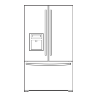
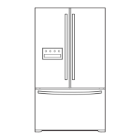
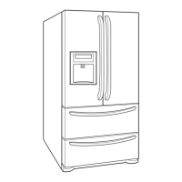
Identification of various refrigerator parts with labels.
Visual representation of ice bucket and ice room door.
Step-by-step guide for removing and replacing refrigerator doors.
Warning about electrical hazards and personal injury during servicing.
Procedures for removing and replacing door gaskets.
Instructions for inserting gasket bracket clips and gasket.
Steps to align refrigerator doors if the space between them is uneven.
Guide for removing the evaporator fan and motor assembly.
Steps for replacing the ice fan scroll assembly.
Procedure for replacing the defrost control assembly.
Instructions for replacing refrigerator and freezer compartment lamps.
Steps to remove the multi duct.
Procedure for replacing the main printed circuit board (PWB).
Steps for disconnecting the dispenser funnel and button assembly.
Guide for replacing the display printed circuit board (PWB).
Steps for replacing the dispenser funnel.
Procedure for replacing the sub PWB for the dispenser.
Steps for replacing the duct door.
Procedure for replacing the ice corner door.
Guide for removing and replacing the icemaker assembly.
Steps for removing the auger motor cover.
Procedure for removing the door ice bin.
Steps for inserting the door ice bin.
Step-by-step instructions for removing the pullout drawer.
Step-by-step instructions for reinstalling the pullout drawer.
Procedure for disassembling the water valve.
Steps for disassembling the fan and fan motor.
Instructions for separating and installing the pullout drawer.
Role, composition, and usage notes for the compressor.
Composition, role, and usage notes for the PTC starter.
Circuit diagram for the PTC starter's effect on the motor.
Explanation of motor restarting and PTC cooling process.
Definition and role of the overload protector (OLP).
Steps for removing the PTC cover.
Troubleshooting steps for compressor and related electric components.
Troubleshooting for other electrical components like fan motors.
A chart for diagnosing service issues based on complaints.
Troubleshooting chart related to the refrigeration cycle.
Diagnostic flow chart for sealed system issues.
Explanation of the icemaker's operational principle.
Description of icemaking, harvest, and fill/park modes.
Details on the icemaking process and sensor usage.
Explanation of the harvest mode for ice removal.
Information on fill/park position and water supply adjustment.
Procedure for performing function tests on the icemaker.
How the automatic diagnosis system works and indicates defects.
List and explanation of error codes for the ice maker.
Basic functions of the appliance, including temperature settings.
Instructions to switch between Fahrenheit and Celsius display.
How to lock/unlock the dispenser and display buttons.
Explanation of the water filter replacement indicator light.
Explanation of the Ultra Ice function for quick freezing.
How to select water or ice from the dispenser.
Operation of the dispenser light modes (Normal, Auto, On).
Control of the freezer fan motor speeds and operation.
Operation of the cooling fan motor in conjunction with the compressor.
Control of the ice compartment fan based on sensor input.
Purpose and operation of the Ultra Ice function.
Explanation of the door open alarm feature and its sounds.
Details on when defrosting starts, stops, and potential malfunctions.
How the automatic diagnosis system works and indicates defects.
List and explanation of error codes for the ice maker.
How to operate and use the product test mode for diagnosis.
Description and voltage breakdown of the power circuit.
Checking load drive conditions and open door detection circuits.
Voltage checks for AC lamp models.
Voltage checks for the freezing compartment fan.
Voltage checks for the machine compartment fan.
Voltage checks for the icing compartment fan.
Checking the open door detection circuit for refrigerator and freezer doors.
Description of the temperature sensor circuits and their readings.
Explanation of the dispenser drive circuit.
Troubleshooting steps when the power source is poor.
Troubleshooting steps when cooling performance is poor.
Troubleshooting steps for incorrect freezer temperature.
Troubleshooting steps when refrigerator temperature is too low.
Troubleshooting steps when defrosting is poor.
Illustration of the main PWB assembly.
List of applicable model numbers for the manual.
List and diagram of valve and water tube parts.
| Brand | Kenmore |
|---|---|
| Model Number | 795.78763.801 |
| Type | French Door |
| Width | 35.75 inches |
| Ice Maker | Yes |
| Water Dispenser | Yes |
| Energy Star Rated/Certified | Yes |
| Color | Stainless Steel |
| Freezer Capacity | 10 cu. ft. |
| Height | 36.25 inches |
| Depth | 36.25 inches |