Do you have a question about the Kenmore Elite 795.71083.01 series and is the answer not in the manual?
Essential safety instructions to follow before servicing the refrigerator.
Instructions for safe power disconnection and important service notices.
Details on electrical ratings, performance, and refrigeration system parameters.
Guidelines for installation clearance and a list of common replacement parts.
Table detailing various physical dimensions of the refrigerator.
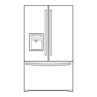
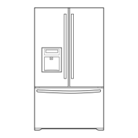
Labeled diagram of refrigerator parts for identification.
Step-by-step guide for safely removing and reinstalling refrigerator doors.
Safety warning regarding explosion hazard during disassembly.
Procedures for removing and installing the refrigerator door gasket.
Steps to align refrigerator doors if the gap is uneven.
Procedure for disassembling the evaporator fan and motor assembly.
Steps to replace the ice fan scroll assembly.
Information on the defrost control assembly and its components.
Instructions for replacing refrigerator and freezer compartment lamps.
Steps for removing the multi duct and accessing the main PWB.
Instructions for disassembling the dispenser and replacing the display PWB.
Procedures for replacing the sub PWB and duct door.
Steps for replacing the ice corner door and icemaker assembly.
Procedure for removing the auger motor cover.
Steps for removing and inserting the ice bin from the door.
Detailed steps for removing the pullout drawer.
Detailed steps for reinstalling the pullout drawer.
Procedure for disassembling the water valve.
Method for disassembling the fan and fan motor.
Instructions for separating and installing the pull out drawer.
Explains the compressor's role, composition, and usage precautions.
Details the PTC starter's composition, role, and operating notes.
Circuit diagram illustrating the PTC starter's application.
Defines the Overload Protector (OLP) and its function.
Steps to remove the PTC cover.
Comprehensive circuit diagram of the refrigerator's electrical systems.
Diagnostic steps for issues related to the compressor and electric components.
Troubleshooting for fans, defrost systems, and other electrical parts.
A chart to diagnose common refrigerator problems and their solutions.
Troubleshooting chart for refrigeration cycle problems like leakage and clogs.
Diagnostic flowchart for problems within the sealed refrigeration system.
Explanation of the icemaker's operational principle and modes.
Details on Icemaking, Harvest, and Fill/Park modes of the icemaker.
How to perform function tests on the icemaker.
Error codes and diagnosis for the ice maker water supply control panel.
Description of the main functions controlled by the MICOM system.
How to toggle display units, lock controls, and use the filter indicator.
How to use dispenser functions like water/ice selection and Ultra Ice.
Control methods and speeds for the freezer fan motor.
Detailed explanation of the Ultra Ice function's operation and timing.
How the open door alarm works and how to set display modes.
Explanation of how and when the automatic defrosting cycle operates.
How the system performs defect diagnosis and displays error codes.
Table detailing error codes, their causes, and remarks for the display panel.
Procedures for operating the various diagnostic test modes.
Diagram and description of the refrigerator's power circuit.
Circuit details for load, fan, and door open detection.
Specifications for machine compartment and icing compartment fan operation.
Circuit check procedure for the open door detection system.
Diagram and explanation of the refrigerator's temperature sensor circuits.
Table of sensor resistance values at different temperatures for diagnostics.
Circuit diagram for the refrigeration compartment stepping motor damper.
Circuit diagram for the dispenser drive components like auger motor and valves.
Circuit diagram for the LED module in the refrigerator/freezer room.
Troubleshooting for power source problems and poor cooling.
Steps for diagnosing and resolving incorrect freezer temperature issues.
Troubleshooting steps for cooling issues when refrigerator temperature is too low.
Troubleshooting steps for issues related to the defrosting system.
Diagram of the Main PWB assembly with component layout.
Diagram of the Dispenser Drive PWB assembly.
Information on ordering repair parts from Sears and contact details.
Parts list and diagrams for valve and water tube components.
Exploded view diagram of case parts with location numbers.
Detailed list of case parts with part numbers and descriptions.
Continuation of the detailed list of case parts.
Exploded view diagram of freezer parts with location numbers.
Exploded view diagram of refrigerator parts with location numbers.
Exploded view diagram of door parts with location numbers.
Detailed list of door parts with part numbers and descriptions.
Exploded view diagram of dispenser parts with location numbers.
Exploded views and lists for ice maker and ice bank components.
| Brand | Kenmore |
|---|---|
| Model | Elite 795.71083.01 series |
| Category | Refrigerator |
| Language | English |