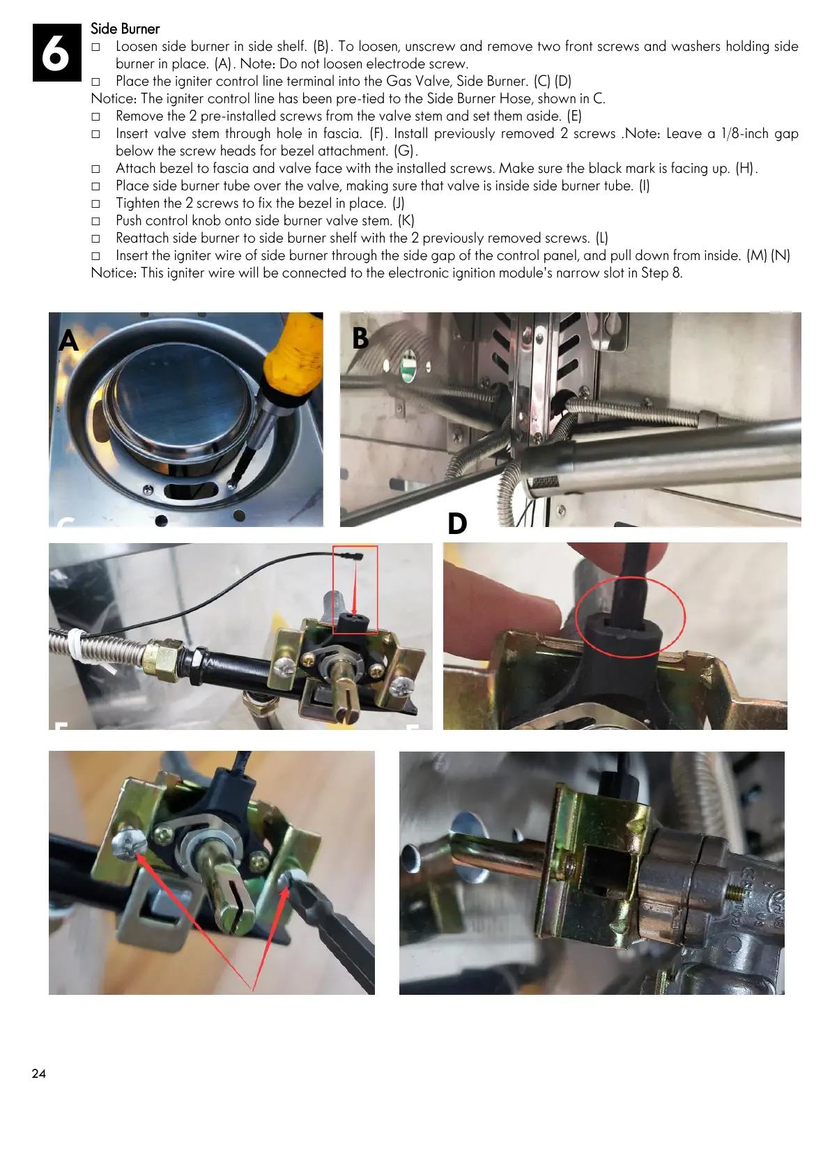
Side Burner
□ Loosen side burner in side shelf. (B). To loosen, unscrew and remove two front screws and washers holding side
burner in place. (A). Note: Do not loosen electrode screw.
□ Place the igniter control line terminal into the Gas Valve, Side Burner. (C)(D)
Notice: The igniter control line has been pre-tied to the Side Burner Hose, shown in C.
□ Remove the 2 pre-installed screws from the valve stem and set them aside. (E)
□ Insert valve stem through hole in fascia. (F). Install previously removed 2 screws .Note: Leave a 1/8-inch gap
below the screw heads for bezel attachment. (G).
□ Attach bezel to fascia and valve face with the installed screws. Make sure the black mark is facing up. (H).
□ Place side burner tube over the valve, making sure that valve is inside side burner tube. (I)
□ Tighten the 2 screws to fix the bezel in place. (J)
□ Push control knob onto side burner valve stem. (K)
□ Reattach side burner to side burner shelf with the 2 previously removed screws. (L)
□ Insert the igniter wire of side burner through the side gap of the control panel, and pull down from inside. (M)(N)
Notice: This igniter wire will be connected to the electronic ignition module’s narrow slot in Step 8.