FOR SERVICE TECHNICIAN’S USE ONLY PART NO. W10035270
TECH SHEET - DO NOT DISCARD PAGE 8
TEST #3b Blower Motor (Dual
Motor Model)
1. Access the motor control electronics. See
Accessing & Removing the Electronic
Assemblies, page 11.
2. Visually check the communication har
-
ness. See figure 15, page 12. The com
-
munication harness is a three-wire har-
ness that connects between the two elec-
tronic control assemblies. Make sure it is
fully inserted into both electronic controls.
3. If the communication harness looks OK,
go to step 4.
4. Visually check the wire harnesses
connected to the motor control electronic
assembly. Make sure they are clean and
fully inserted into the control.
➔
If the connections look OK, go to
step 5.
5. Remove the MC2 blower motor electrical
connector from the blower motor
electronic control.
6. Measure the resistance between the fol
-
lowing terminals on the connector: pins
1 to 3, 1 to 5 and 3 to 5. The resistance
should be between 55 and 65 ohms.
➔ If the resistance looks OK, go to
step 7.
➔ If the resistance is much greater than
65 ohms, go to step 7.
➔ If the resistance is much less than
55 ohms, replace the blower motor.
7. Visually check the wire harness
connection at the blower motor (See
Accessing the Blower Motor below).
➔ If the connections look OK, check for
obstructions in the blower housing.
Make sure blower fan rotates freely.
➔
If no obstructions are found, replace
the motor control electronic assembly.
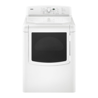
Accessing the Blower Motor:
Follow the steps under Removing the Front
Panel/Drum Assembly, page 11. The blower
motor is located on top of the blower
housing as shown in figure 9.
TEST #4 Heater
This test is performed when either of the
following situations occur:
✔
Dryer does not heat
✔
Heat will not shut off
This test checks the components making up
the heating circuit. The following items are
part of this system:
–
Harness/
connection
–
Heater relay
–
Thermal cut-off
–
Inlet thermistor/
high limit
thermostat
–
Heat element
assembly
–
Centrifugal switch
–
Exhaust thermistor
–
Machine control
electronics. See
ESD information,
page 1.
–
User interface
assembly
Dryer does not heat:
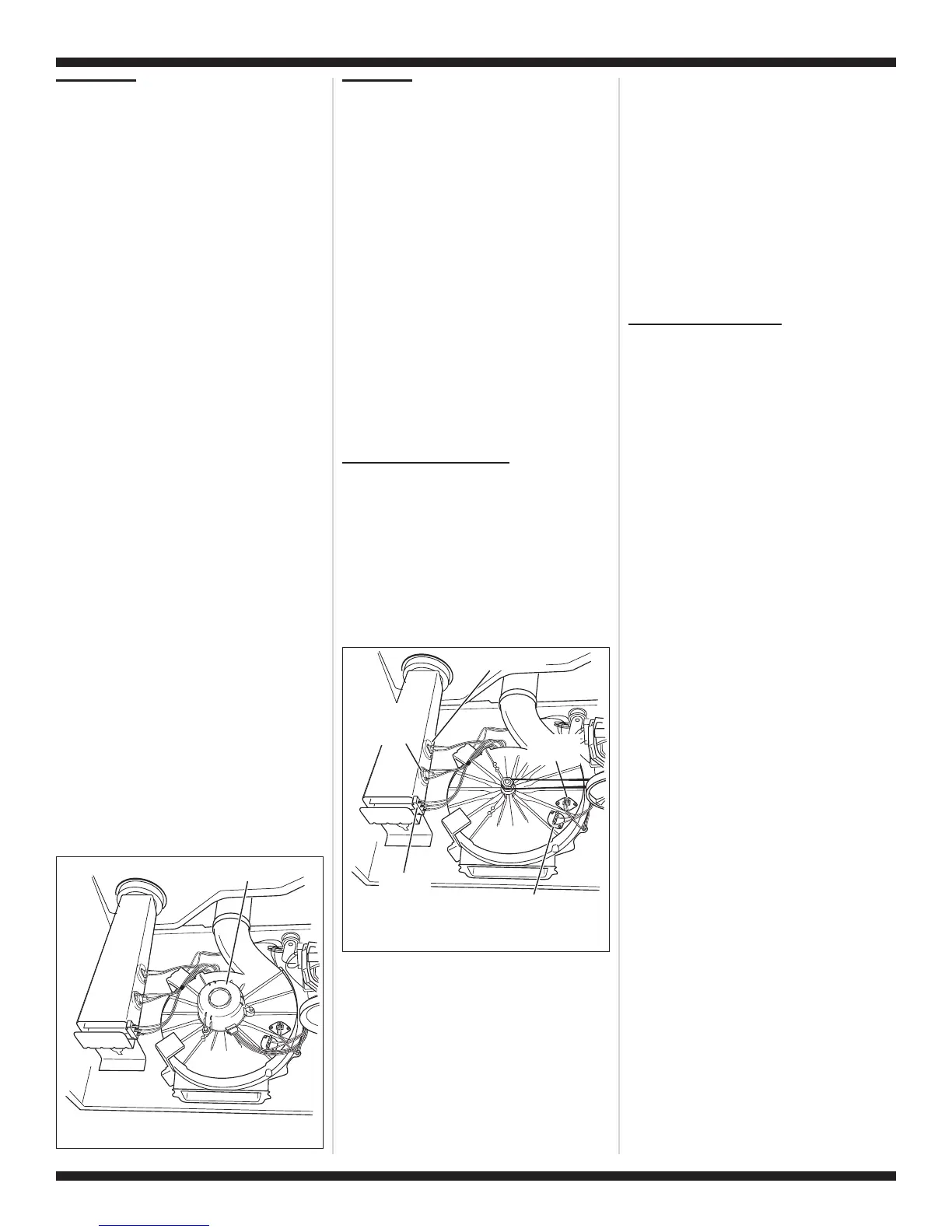
Locate the components using figure 2,
page 6; and figure 10.
SINGLE ELEMENT MODEL
:
1. Unplug dryer or disconnect power.
2. Remove the front panel and drum
assembly to access the thermal
components. See Removing the Front
Panel/Drum Assembly, page 11.
3. Using an ohmmeter and referring to the
appropriate wiring diagram and strip cir-
cuit, pages 4 and 5, measure the resis-
tance from the red wire terminal at the
thermal cut-off to the red wire terminal at
the heater.
➔
If the resistance is about 10 ohms, go
to step 5.
➔
If an open circuit is detected, go to
step 4.
4. Visually check the wire connections to the
thermal cut-off, high limit thermostat, and
heater. If connections look good, check
for continuity across each of these
components.
➔
Replace the heater if it is electrically
open.
➔
Replace both the thermal cut-off and
high limit thermostat if either one is
electrically open.
5. If no open circuit is detected, remove the
P4 connector, then measure the
resistance between P4-3 (red wire) and
P4-6 (red wire) at the connector. See
figure 16, page 12 for connector location;
and Accessing & Removing the
Electronic Assemblies, page 11.
➔
If 5–15 k ohms are measured, replace
the machine control electronics.
➔
If the resistance is less than 1 k ohm,
replace the thermistor.
DUAL ELEMENT MODEL
:
1. Unplug dryer or disconnect power.
2. Remove the front panel/drum assembly
to access the thermal components. See
Removing the Front Panel/Drum
Assembly, page 11.
3. Using an ohmmeter and referring to the
appropriate wiring diagram and strip
circuit, pages 4 and 5, measure the
resistance from the black wire terminal at
the thermal cut-off to the red wire terminal
at the high limit thermostat.
➔
If an open circuit is not detected, go to
step 5.
➔ If an open circuit is detected, go to
step 4.
4. Visually check the wires connections to
the thermal cut-off and the high limit
thermostat. If connections look good,
check for continuity across each of these
components. Replace both the thermal
cut-off and high limit thermostat if either
one is electrically open.
5. Measure the resistance between the red
wires at the heater.
➔
If an open circuit is not detected, go to
step 7.
➔
If an open circuit is detected, go to
step 6.
6. Visually check the wire connections to
the heater. If the connections look good,
replace the heater.
7. Measure the resistance at the heater
between the violet wire and the red wire
with the larger terminal.
➔
If an open circuit is not detected, go to
step 9.
➔
If an open circuit is detected, go to
step 8.
8. Visually check the wire connections to
the heater. If the connections look good,
replace the heater assembly.
9. If no open circuit is detected, remove the
P4 connector, then measure the
resistance between P4-3 (red wire) and
P4-6 (red wire) at the connector. See
figure 16, page 12 for connector location;
and Accessing & Removing the
Electronic Assemblies, page 11.
➔
If 5–15 k ohms are measured, replace
the machine control electronics.
Blower Motor
Figure 9. Blower motor location.
Thermal Fuse
Exhaust
Thermistor
Inlet Thermistor/
High Limit
Thermostat
Thermal Cut-Off
Heater
Element
Figure 10. Thermal components,
viewed from front.