Kenwood BASIC M1 Current Source Modification
www.drmaudtioht.com
10/9/2008 6:56 PM page 6 of 10
Instructions
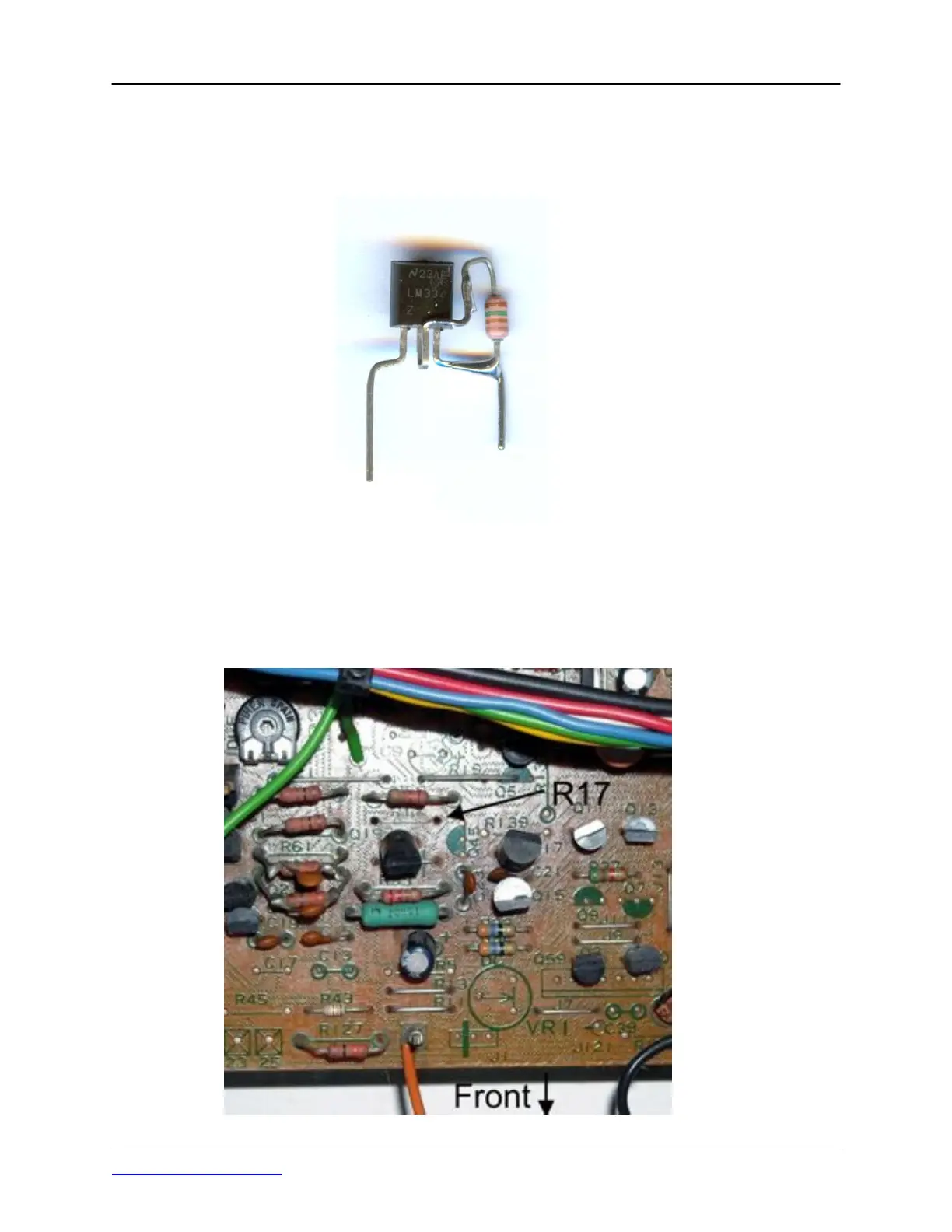
Step 1 - Form the leads of the two LM334Z devices that are in a TO92 plastic case and solder a 150 1/4
watt carbon film resistor to the formed leads as shown in this photo:
Note that the resistor is connected between the center lead, which is pin 2 of the device and pin 3. You
can form the leads as you desire, just maintain the lead spacing of .400 inches so the devices will fit in
the holes in the boards that were originally occupied by R17 and R18.
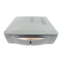
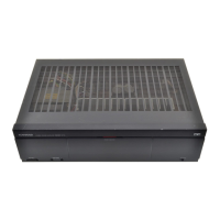
Step 2 - Remove R17 and R18. This photo shows the top side of the amplifier pc board assembly with
the original current source resistor R17 removed: