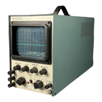
The CO-1506 is a 130mm oscilloscope designed for general-purpose electronic measurements, offering a balance of performance and ease of use. It is particularly well-suited for observing and analyzing waveforms in various electronic circuits.
Function Description
The primary function of the CO-1506 oscilloscope is to visualize electrical signals as waveforms on a Cathode Ray Tube (CRT) display. This allows users to measure voltage, frequency, and phase relationships of signals, as well as observe signal characteristics such as amplitude, rise time, and distortion. It features both vertical and horizontal amplification, a sweep circuit for time-base generation, and synchronization capabilities to stabilize displayed waveforms. The device can display both AC and DC components of signals, making it versatile for different measurement needs. It also supports Lissajous figures for frequency and phase difference measurements, and can be used for aligning AM/FM receivers and checking amplifier frequency response.
Important Technical Specifications
Vertical Amplifier
- Deflection Sensitivity: 20 mV/cm or more
- Frequency Response: DC to 1.5 MHz (–3dB) for DC coupling; 2 Hz to 1.5 MHz (–3dB) for AC coupling.
- Input Resistance: 1 MΩ (±5%)
- Input Capacitance: Approx. 35 pF
- Attenuator: 1, 1/10, 1/100 (within ±5% inter-range error)
- Gain Control: Variable up to 22dB or more
- Permissible Input Voltage: 600 Vp-p (DC + AC peak)
- Drift: Thermal: 1 mm/°C or less at 20mV/cm; Time: 15 mm/hr or less 15 min. after switch on; 5% or less on 100kHz square wave overshoot.
Horizontal Amplifier
- Deflection Sensitivity: 500 mV/cm or more
- Frequency Response: DC to 250kHz (–3dB) at the maximum point of H. GAIN control.
- Input Resistance: 1 MΩ (±20%)
- Input Capacitance: Approx. 40pF
- Permissible Response: 100 Vp-p
Sweep Circuit
- Sweep Frequency: 10 to 100 Hz, 100 to 1 kHz, 1 to 10 kHz, and 10 to 100 kHz (continuously adjustable between ranges).
- Synchronizing: Internal negative synchronizing possible with 10 mm amplitude or less on CRT screen.
Power Source
- AC100V/117V/230V, 50/60Hz
Power Consumption
Dimensions
- Maximum Width: 150mm (154 mm)
- Maximum Height: 220 mm (246 mm)
- Maximum Depth: 410 mm (445 mm)
- Values in ( ) are maximum dimensions.
Weight
Accessories
- Instruction manual: 1
- Fuse (0.3A – in the area of 230V power supply): 2
- Fuse (0.5A – in the area of 117V power supply): 2
- Shielded lead with banana plug (CA-46): 1
Usage Features
The CO-1506 is designed for straightforward operation with clearly labeled controls.
- Waveform Display: Signals are fed into the V. INPUT terminals (AC or DC) and GND. The VERT. ATT and V. GAIN controls adjust the vertical amplitude to fit the display, typically 40-60 mm high.
- Synchronization: The SWEEP RANGE and VAR/H. GAIN controls are used to obtain a stable, synchronized waveform. The sweep frequency can be matched to the signal frequency for a single cycle display or set to show multiple cycles.
- DC Component Measurement: By using the V. INPUT DC terminal, the DC component of a waveform can be measured, and frequencies below 10 Hz can be viewed. The waveform's position can be centered using the (9) and (12) controls.
- Voltage Measurement: Voltage is calculated as "Amplitude x sensitivity." The oscilloscope displays peak-to-peak values, which can be converted to effective (RMS) values based on the waveform type.
- Lissajous Figures: This feature allows for frequency and phase difference measurements. By applying an unknown frequency signal to the V. INPUT and a known signal to the H. INPUT (via EXT position of SWEEP RANGE), various patterns (straight lines, circles, ellipses) appear, from which the unknown frequency can be calculated. Phase difference can also be determined from the shape of the Lissajous figure using the formula Sin θ = x/X, where X is horizontal amplitude and x is horizontal excursion.
- AM/FM Receiver Alignment: The oscilloscope can be used to align IF transformers of AM receivers and check the overall response of IF transformers in FM/TV receivers. This involves connecting a sweep generator and observing the output on the CRT.
- Amplifier Frequency Response: By supplying a sine wave from a signal generator and connecting the amplifier's output to the V. INPUT, the frequency response can be measured by observing the amplitude at different frequencies. Square wave signals can also be used for an approximate frequency response check.
- Modulation Measurement: The CO-1506 can measure modulated carriers below 1.5MHz. By displaying the modulation envelope, the degree of modulation can be calculated from the maximum (A) and minimum (B) values using the formula (A-B)/(A+B) x 100(%). A trapezoidal pattern method is also available for this measurement.
Maintenance Features
The manual provides clear instructions for basic maintenance and adjustments to ensure the oscilloscope's longevity and accuracy.
- Environmental Considerations: The device should be installed in a location not exposed to direct sunlight, high temperature, humidity, mechanical vibrations, or strong magnetic fields to prevent instability or damage.
- Fuse Replacement: Instructions are provided for replacing the fuse, including the correct ampere rating for different power supply voltages (0.3A for 230V, 0.5A for 117V). Users are cautioned to turn off the power and discharge capacitors before replacement.
- CRT Alignment: If the bright line on the CRT is not horizontal, it can be realigned by loosening specific clamping screws (16) and carefully rotating the CRT. Users are warned to avoid touching high-voltage circuits during this process.
- DC BAL Adjustment: This adjustment corrects waveform shifting when the V. GAIN control is turned. It involves setting VERT ATT to GND, V. GAIN to fully counterclockwise, and POSITION to center, then adjusting DC BAL (13) with a screwdriver to eliminate deviation.
- VERT. ATT Adjustment: This adjustment ensures accurate amplitude readings across different attenuation settings. It involves applying a square wave, setting VERT ATT to 1, and adjusting TC1 and TC2 for an ideal waveform at different attenuation levels.
- Overshoot Correction: For a 100kHz square wave, overshoot can be corrected by adjusting TC3.
- Position Control Adjustment: Variable resistors VR4 and VR6 are used to set the bright line in the center of the scope, while VR8 adjusts the sweep width.
- Case Removal: Instructions are given for removing the cabinet and bottom plate to access internal components for maintenance.
Overall, the CO-1506 is a robust and versatile oscilloscope, suitable for a wide range of electronic testing and analysis tasks, with user-friendly controls and clear maintenance guidelines.