EasyManua.ls Logo

Kenwood GE-622 Service Manual

Kenwood GE-622
20 pages
To Next Page IconTo Next Page
Page #1 background imageLoading...
Page #1 background image
GRAPHIC
EQUALIZER
Metallic
cabinet
Knob
(Up)
(A01-2000-01)
:
J
(K29-4162-03)
(A01-1999-01)
:
S
TATTLE
UUUTTULLTTEAEH
ATED)
ATMEL
WMH
>
SYTHUIRUATEA
HCAS
NATTA
TL
PTL
Ue
~
PUTLUATHLAV
ACEH
>
TUSTIN
HVPE
GHTHUATRRETTANHE
Knob
(Effect/5)
(K29-4186-02)
Rectangular
receptacle
(E08-1509-05)
HARUENOUNTELTNTINTE
pIEUATVENTVEEUUETT
AAT:
TTL
HATH
PTTL
sLUTeDRUAgHU
UAT
SUNTAN
HUUUHUU
Knob
(Down)
(K29-4164-03)
(KENWOOD
‘STEREO
GRAPHIC”
EQUALIZER
SERIAL
NO.”
Rectangular
receptacle
(E08-1510-05)
CAUTION
:
When
doing
repair
of
GE-622,
be
sure
to
have
customer
bring
the
A-522,
or
use
power
supply
jig
RM-90PS,
or
supply
to
16V
AC
to
terminal
Nos
15
and
14
in
CN1
on
the
X11-3090
PC
board
ass'y.
If
not
get
16V
AC,
please
order
the
A-848's
power
transformer
(parts
No.
LO7-0038-05
/
120V
/
240V).
Don't
use
the
"RHEOSTAT".
“@ee22
|
Cord
with
connector
(E30-2669-05)
THUR
LUNTUUTTTL:
“TATA
ETE
AUTEHTLCHUL
ULE
Phono
jack
(E63-0023-05)
(E63-0022-05)
©
1991-7
PRINTED
IN
JAPAN
B51-4382-00
(O)
3890
Front
glass
Panel
(B10-1859-03)
(A60-0161-01)
Knob
(Al
auto/Hit
master)*
(K29-)
Phono
jack
{E63-0024-05)
Phono
jack
J=JAPAN
MADE
S=SINGAPORE
MADE
*
Refer
to
parts
list
on
page
24.
Question and Answer IconNeed help?

Do you have a question about the Kenwood GE-622 and is the answer not in the manual?

Kenwood GE-622 Specifications

General IconGeneral
BrandKenwood
ModelGE-622
CategoryRecording Equipment
LanguageEnglish

Summary

Controls and Jig Overview

Front Panel Controls

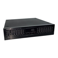
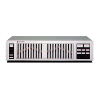
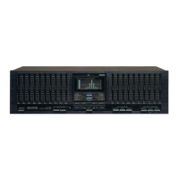
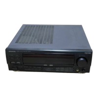
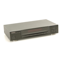
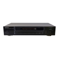
Details the function of various control keys on the front panel.

Power Transformer Jig

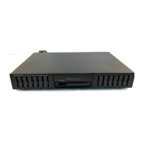
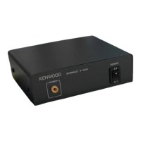
Illustrates the power transformer and its connection jig for testing.

Circuit Description: Audio Line Block Diagram

Circuit Description: Display Control Diagram

Circuit Description: Main Microprocessor

Circuit Description: Terminal Details

Circuit Description: Input Sensitivity

Test Mode Procedures

Test Mode Operation Methods

Describes how to set and operate different test modes.

Test Mode Release and Setup

Details methods for exiting test mode and initial setup.

Display Microprocessor: Terminal Diagram

Exploded View of Unit Components

Parts List: Japan Made Components

Parts List: Singapore Made Components

Parts List: Electronic Components and ICs

Specifications and Component Data

Equalizer and Loudness Characteristics

Details variable ranges and AI Loudness control specifications.

Dimensions, Weight, and Component Coding

Lists unit dimensions, weight, and component coding conventions.
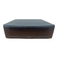
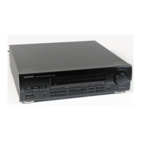
Related product manuals