EasyManua.ls Logo

Kenwood HM-901 User Manual

Kenwood HM-901
23 pages
To Next Page IconTo Next Page
Page #1 background imageLoading...
Page #1 background image
PRECAUTIONS FOR REPAIR
• For the SERIAL TEST CODE LIST of the circuit description, see Service manual (B51-5210-00) of R-SA7.
• For the INITIAL STATE, the BACK UP and the MICROPROCESSOR of the circuit description, see Service manual (B51-
5373-00) of R-SE7.
• No connection of ground line if disassemble the unit.
• Please connection the ground line on rear panel, PCBs, Chassis and some others.
STEREO INTEGRATED AMPLIFIER/TUNER
R-SE9
SERVICE MANUAL
©1997-10/B51-5375-00 (K/K) 888
band
volume control
auto/mono enter
phones
mode
pure
multi control
N.B.
down up
stereo integrated amplifier/tuner R-SE9
A
TRAITR
on/standby
SYSTEM
CONTROL
ANTENNA
AM
GND
FM75
CD
IN IN
REC PLAY
SUPER
WOOFER
PRE OUT
SPEAKERS
( 6 - 16 )
L
R
TAPE
REC PLAY
MD
AUX
R
L
Side plate
(A50-1303-02)
Panel*
(A60-)
Front glass
(B10-2369-03)
AC power cord *
(E30-)
Screw terminal board
(E70-0061-05)
Lock terminal board
(E20-0476-05)
Phono jack
(E63-1014-05)
Phono jack
(E63-0046-15)
Phono jack
(E63-0047-15)
Rectangular receptacle
(E08-0312-05)
Metallic cabinet
(A01-3463-11)
Power cord bushing
(J42-0083-05)
Knob
(K29-6741-04)
Knob
(K29-6738-04)
Knob
(K29-6739-04)
Knob
(K29-6751-04)
(HM-901)
* Refer to parts list on page 21.
R-SE9(K) 1P 97.11.29 3:34 AM y[W 2
Question and Answer IconNeed help?

Do you have a question about the Kenwood HM-901 and is the answer not in the manual?

Kenwood HM-901 Specifications

General IconGeneral
BrandKenwood
ModelHM-901
CategoryAmplifier
LanguageEnglish

Summary

Service Manual Introduction and Precautions

Repair Safety Guidelines

Safety precautions for repair, including grounding and serial test code notes.

System Contents and Accessories

Included Accessories

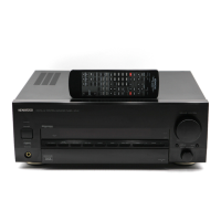
Lists items like antennas, audio cords, remote control, and battery cover.

Circuit Description

Tuner and Test Mode Details

Covers tuner destination list, initialization, and AMP test mode.

Advanced Test Modes and Operations

Explains AMP test mode operations and serial test mode procedures.

Adjustment Procedures

FM and Audio Section Tuning

Details discriminator, distortion, and idle current adjustments.

Adjustment Setup and Connections

Illustrates system connections for performing adjustments.

Exploded View and Part Identification

Unit Assembly Diagram

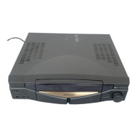
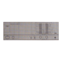
Visual breakdown of the unit with numbered parts for assembly reference.

Parts List

Cabinet, Panel, and Tuner Components

Lists cabinet, panel, tuner unit parts, and their specifications.

Audio Unit, Resistors, and Diodes

Details audio components, resistors, capacitors, and diodes.

Capacitors, Connectors, and Switches

Lists capacitors, connectors, fuses, and various switches.

Display Unit and Input Components

Covers display unit parts, rotary encoders, and opto-isolators.

Technical Specifications

Amplifier and Tuner Performance

Details amplifier output, THD, tuner sensitivity, selectivity, and stereo separation.

General Unit Data

Includes power consumption, dimensions, weight, and AM tuner specs.

Manufacturer and Service Information

Global Service Network

Lists KENWOOD service corporations and branches worldwide.

Related product manuals