Do you have a question about the Kenwood KAC-629S and is the answer not in the manual?
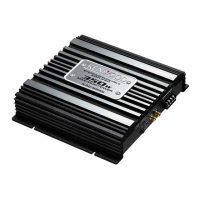
Identifies the KAC-629S model power amplifier and manufacturer.
Lists the screw set and terminal cover set provided with the amplifier.
Visual representation of the amplifier's internal signal flow and major components.
Details the procedure for setting the idle current using a DC voltmeter.
Explains the coding system for identifying capacitor values, tolerance, and temperature coefficients.
Details the coding system for identifying resistor values and ratings.
Diagram showing the placement of components on the printed circuit board.
Diagram illustrating the copper traces and connections on the underside of the PCB.
Detailed electrical schematic showing the amplifier's circuit design and component interconnections.
Illustrates the mechanical assembly of the amplifier with numbered parts.
Provides a reference for part numbers and their corresponding descriptions.
Lists capacitors (Cxx) and connectors (CNxx, Jx, TP1) with their part numbers and specifications.
Details components like LED, choke coil, and transformer for the audio unit.
Lists resistors (Rxx) and diodes (Dxx) with their part numbers and specifications.
Lists transistors (Qxx) and integrated circuits (ICx) with their part numbers and types.
Details power output, frequency response, sensitivity, and filter characteristics.
Covers operating voltage, current consumption, dimensions, and weight.
| max power output (4Ω) normal | 120W x 2 |
|---|---|
| max power output (4Ω) bridge | 350W x 1 |
| rated power output (4Ω) normal (20Hz-20KHz, 0.08% THD) | 60W x 2 |
| rated power output (4Ω) normal (DIN45324, +B=14.4V) | 60W x 2 |
| rated power output (4Ω) bridge (1KHz, 0.8% THD) | 150W x 1 |
| rated power output (2Ω) normal (1KHz, 0.8% THD) | 75W x 2 |
| frequency response (+0, -1dB) | 10Hz - 45kHz |
| signal to noise ratio | 100dB |
| sensitivity (MAX) (rated output) | 0.2V |
| sensitivity (MIN) (rated output) | 5.0V |
| input impedance | 10kΩ |
| low pass filter (12dB/oct.) | 80Hz |
| high pass filter (12dB/oct.) | 150Hz |
| operating voltage | 14.4V |
|---|---|
| current consumption (1KHz, 10% THD) | 19A |
| dimensions (Width x Height x Depth) | 221mm x 57mm x 228mm |
| weight | 2.8kg |