© 2002-11 PRINTED IN JAPAN
B51-7994-00
(
N
)
3379
CD AUTO CHANGER
KDC-C469/Y/FM/FMA
KDC-C669/Y
SERVICE MANUAL
COMPACT DISC AUTO CHANGER KDC-C669
NEW ANTI VIBRATION MECHANISM DISC NAME PRESET
TEXT
6
DISC
COMPACT
DIGITAL AUDIO
CD-R/RW
COMPACT DISC AUTO CHANGER KDC-C469
NEW ANTI VIBRATION MECHANISM DISC NAME PRESET
6
DISC
COMPACT
DIGITAL AUDIO
CD-R/RW
COMPACT DISC AUTO CHANGER KDC-C469FM
NEW ANTI VIBRATION MECHANISM
6
DISC
COMPACT
DIGITAL AUDIO
CD-R/RW
1BIT 4D/A CONVERTER
COMPACT
DIGITAL AUDIO
PWR
TRACK DISC
RDM
REP
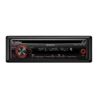
Illustration is
KDC-C469FM/FMA.
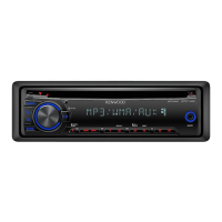
Illustration is
KDC-C669/Y.
HOLDER ASSY
(J19-5149-02)
TRAY
(J99-0614-01)
CORD WITH PLUG
(E30-4291-05
or E30-4954-15)
When transporting these models, always attach CAUTION CARD and STEPPED SCREW (for transportation).
The MECHANISM OPERATION is the same as model KDC-C660.
Please refer to the service manual of model KDC-C660 (B51-7105-00).
Service jig
W05-0635-00
Parts No.
For initial position setting
BRACKET (R)
(J19-5021-03)
BRACKET (L)
(J19-5020-03)
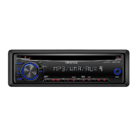
Illustration is
KDC-C469/Y.
SCREW SET
(N99-1645-15)
REMOTO
CONTROLLER ASSY
(A70-2032-05)
RC-504FM
: KDC-C469FM/FMA (E)
BATTERY (SIZE:AAA)
Not supplied as
service parts
DISPLAY UNIT ASSY
(T95-0247-08)
: KDC-C469FM (K)
(T95-0244-08)
: KDC-C469FM (E)
(T95-0251-08)
: KDC-C469FMA (E)
CASE
(A01-2819-08)
: KDC-C469FM (K)
(A01-2824-08)
: KDC-C469FM/FMA (E)
HOLDER ASSY
(B07-2138-08)
: KDC-C469FM/FMA
ANTENNA
ADAPTOR
(T90-0512-05)
: KDC-C469FM/FMA (E)
ANTENNA
ADAPTOR
(T90-0521-05)
: KDC-C469FM/FMA (E)
MAGICTAPE ASSY
(W01-0763-08)
: KDC-C469FM/FMA
w
w
w
.
x
i
a
o
y
u
1
6
3
.
c
o
m
Q
Q
3
7
6
3
1
5
1
5
0
9
9
2
8
9
4
2
9
8
T
E
L
1
3
9
4
2
2
9
6
5
1
3
9
9
2
8
9
4
2
9
8
0
5
1
5
1
3
6
7
3
Q
Q
TEL 13942296513 QQ 376315150 892498299
TEL 13942296513 QQ 376315150 892498299