This document provides detailed instructions for the disassembly and re-assembly of Kenwood Sovereign kitchen machines, specifically models KM001, KM002, KM003, KM502, KM005, KM006, and KM007. The guide is structured into sections covering different components of the appliance: Top Cover, Pedestal, Motor, Gearbox, Latch Assembly, and Speed Control Knob. Each section outlines the steps required to remove and re-install the respective parts, often accompanied by illustrative images and specific tool recommendations.
Function Description:
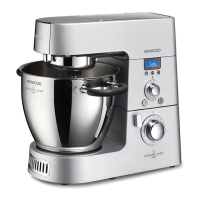
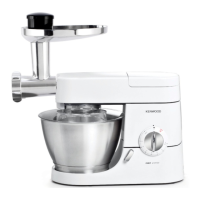
The Kenwood Sovereign kitchen machine is a versatile appliance designed for various food preparation tasks. Its core function involves a motor-driven head that can be raised and lowered, accommodating different attachments for mixing, kneading, and other processes. The machine features multiple outlets for accessories, including a high-speed outlet and a slow-speed outlet, indicating its capability to handle a range of culinary functions from blending to mincing. The speed control knob allows for precise adjustment of the motor's operation, enabling users to tailor the machine's performance to specific tasks. The robust design, including a pedestal for stability and a gearbox for power transmission, suggests its suitability for demanding kitchen environments.
Important Technical Specifications (Inferred from instructions):
- Screwdriver Types: The instructions frequently specify the use of No.2 Pozidrive, TX15, and TX20 screwdrivers for various screws, indicating the types of fasteners used in the appliance's construction.
- Nut Size: An 8mm hex nut is mentioned for the location pin, providing a specific fastener detail.
- Motor: The motor is a key component, with instructions for removing its screws, belt, and brushes. It is connected to a fan and pulley system, which requires a press for replacement to avoid damage.
- Gearbox: The gearbox is a critical power transmission component, featuring a large pulley that can be removed using a stall plug or a mincer attachment to prevent rotation.
- Electrical Components: The presence of a speed control module, sensors, motor supply, and power supply connectors indicates a sophisticated electrical system for precise operation. The potentiometer within the speed control knob is pre-set for correct pulse operation, highlighting its electronic control.
- Safety Features: Warnings about restraining the pedestal during head release and taking care to avoid scratching the body with the head lift mechanism emphasize built-in safety considerations for both the user and the appliance during maintenance.
Usage Features (Inferred from disassembly/re-assembly context):
- Head Release Mechanism: The machine features a head release mechanism that allows the head to be raised and lowered, likely for easy attachment and removal of accessories, and for bowl access. This mechanism requires careful operation and restraint of the pedestal to prevent violent springing.
- Multiple Outlets: The mention of a high-speed outlet and a slow-speed outlet implies the machine's compatibility with a wide array of attachments, each designed for specific speed requirements.
- Speed Control: The speed control knob allows users to adjust the operating speed. The potentiometer is pre-set for "pulse operation" rather than a direct link to speed, suggesting advanced control for intermittent power bursts.
- Attachment Compatibility: The instructions mention using a mincer attachment as a tool for gearbox pulley removal, demonstrating the machine's modular design and the utility of its attachments beyond their primary function.
Maintenance Features:
- Modular Design: The appliance is designed with modular components (Top Cover, Pedestal, Motor, Gearbox, Latch Assembly, Speed Control Knob) that can be individually disassembled and re-assembled, facilitating targeted repairs and maintenance.
- Tool Specificity: The guide provides precise tool recommendations (e.g., No.2 Pozidrive, TX15, TX20 screwdrivers, 8mm hex nut wrench), ensuring that technicians use the correct tools to prevent damage during maintenance.
- Re-assembly Cautions: Specific warnings are given for re-assembly, such as avoiding disturbance of the anti-vibration cap on the gearbox and ensuring the power supply cable does not rub on the fan. These details are crucial for maintaining the appliance's performance and longevity.
- Specialized Procedures: Certain tasks, like replacing the fan and pulley, require specialized equipment (a press) to prevent damage to the motor. This indicates that some maintenance operations are intended for trained technicians.
- Electrical Component Handling: The guide instructs on disconnecting and reconnecting three connectors (sensors, motor supply, power supply), highlighting the need for careful handling of electrical components during maintenance.
- Potentiometer Adjustment: The potentiometer in the speed control knob is pre-set, and its adjustment requires "special training," indicating that this is a sensitive calibration best left to qualified personnel.
- Troubleshooting Clues: The mention of "belt wear on the body" as a potential sign of motor damage due to shock loads provides a diagnostic clue for technicians.
- Screw Tray Suggestion: The instruction to use the removed box as a "screw tray" is a practical tip for organizing fasteners during disassembly, improving efficiency and preventing loss of small parts.