Do you have a question about the Kenwood KRC-179RYG and is the answer not in the manual?
| Model | KRC-179RYG |
|---|---|
| DIN Size | 1 DIN |
| Channels | 4 |
| Peak Power Output | 50W x 4 |
| Preamp Voltage | 2V |
| CD Player | Yes |
| CD-R/RW Playback | Yes |
| MP3 Playback | No |
| WMA Playback | No |
| AM/FM Tuner | Yes |
| Clock | Yes |
| Detachable Face | Yes |
| Remote Control | No |
| Type | Car Stereo |
| RMS Power Output | 22W |
| RMS Power | 22W x 4 |
| Preset Stations | 24 |
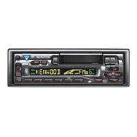
| Display Illumination | Green |
Details functional components and their roles within the synthesizer unit.
Details the terminals and functions of the µ-COM IC for system control.
Instructions for entering and exiting the diagnostic test mode.
Procedures for adjusting audio settings within the test mode.
Details the procedure for aligning the head angle for proper tape playback.
Step-by-step guide for aligning head height during tape transport.
Describes capacitor and resistor types, dimensions, and values.
Shows the foil (copper trace) side of the printed circuit board for troubleshooting.