Do you have a question about the Kenwood KSC-WD250 and is the answer not in the manual?
| maximum output | 200W |
|---|---|
| power voltage | DC14.4V |
| operational voltage range | 10.5 - 16V |
| maximum current consumption | 10A |
| fuse capacity | 5A x 2 |
| frequency response | 30-150Hz |
|---|---|
| signal to noise ratio | 85dB |
| low pass filter frequency | 50Hz, 80Hz, 100Hz, 150Hz |
| phase | 0°, 180° |
| sensitivity/input impedance (RCA pinjack) | 210mV/10kΩ |
| sensitivity/input impedance (speaker input) | 4.2V/1kΩ |
| impedance | 0.75Ω |
|---|---|
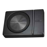
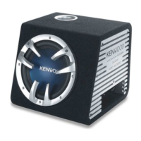
| woofer size | 10 inch |
| external size (amp unit) | 195mm x 30mm x 155mm |
|---|---|
| weight (amp unit) | 800g |
| external size (amp unit + speaker unit) | 353mm x 327.5mm x 371.7mm |
| net weight (amp unit + speaker unit) | 11.5kg |
Safety warnings for mounting, wiring, preventing short circuits, and handling potential smoke or abnormal smells.
Precautions regarding installation locations, fuse replacement, cleaning, and connecting cables to prevent damage.
Notice regarding radio frequency energy and potential interference from unauthorized modifications.
Guidance on operating the unit after the car interior has cooled down from high temperatures.
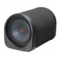
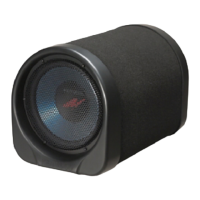
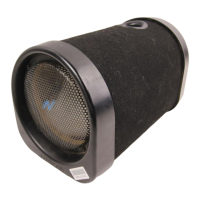
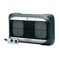
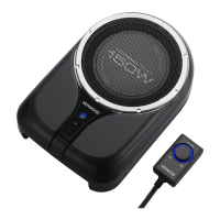
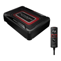
List of all components provided with the subwoofer unit.
Illustrates the standard wiring method for connecting the unit to a car stereo system.
Shows how to connect for subwoofer control via the center unit's non-fader output.
Detailed wiring diagram for connecting the unit to the car's power and audio system.
Wiring diagram for connecting to a center unit with subwoofer control capabilities.
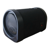
Identifies and labels the various controls and terminals on the unit.
Instructions for setting crossover frequency, low frequency level, and phase.
Procedure for safely replacing the fuse with one of the correct capacity.
Guidance on connecting the remote control unit to the main unit.
Instructions for mounting the remote control unit in the vehicle using Velcro tape.
Troubleshooting steps for when the unit's power indicator does not light up.
Steps to diagnose and resolve issues where no sound is produced.
Solutions for problems related to bad sound quality or distorted audio.
Troubleshooting for situations where the unit cannot be controlled properly.