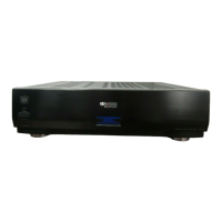
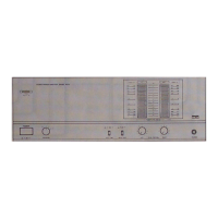
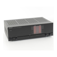
KMF-X9000/MX-5000
2
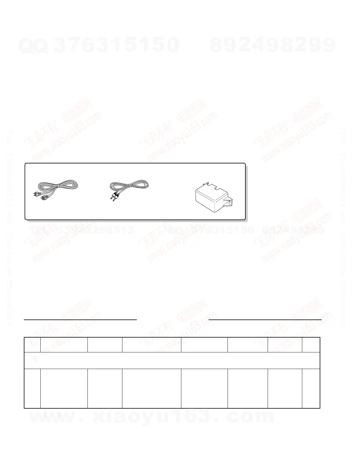
Audio cord (1)
(E30-0505-05)
Stereo mini-plug cord (1)
(E30-2733-05)
Speaker terminal cover (1)
(A09-1247-08)
CONTENTS / ACCESSORIES
CONTENTS / ACCESSORIES .................................. 2
ADJUSTMENT ............................................................2
PC BOARD ................................................................ 3
SCHEMATIC DIAGRAM ............................................ 7
EXPLODED VIEW ......................................................9
PARTS LIST..............................................................10
SPECIFICATIONS ......................................Back cover
Contents
Accessories
ADJUSTMENT
No. ITEM
INPUT
SETTINGS
OUTPUT
SETTINGS
AMPLIFIER
SETTINGS
ALIGNMENT
POINT
ALIGN FOR FIG.
1 IDLE CURRENT –
Connect a DC voltmeter
between pin 1 and pin 2
of connectors.
CN107 (Lch)
CN106 (Rch)
No signal input
VR107(L)
VR106(R)
20 mV
Unless otherwise specified, the individual switches should be set as following:
POWER: ON
w
w
w
.
x
i
a
o
y
u
1
6
3
.
c
o
m
Q
Q
3
7
6
3
1
5
1
5
0
9
9
2
8
9
4
2
9
8
T
E
L
1
3
9
4
2
2
9
6
5
1
3
9
9
2
8
9
4
2
9
8
0
5
1
5
1
3
6
7
3
Q
Q
TEL 13942296513 QQ 376315150 892498299
TEL 13942296513 QQ 376315150 892498299