Do you have a question about the Kenwood NX-220 and is the answer not in the manual?
Manual's intended audience and scope.
Procedures for ordering spare parts and equipment.
Recommended precautions for personal safety during operation.
Information on servicing and alignment procedures.
Description of various operating modes for the transceiver.
Instructions on how to access different operational modes.
Procedure for entering and operating Panel Test Mode on C models.
Procedure for entering and operating Panel Tuning Mode on C models.
Explanation of using the transceiver with a PC for programming.
Introduction to PC mode setup and requirements.
Steps for connecting the transceiver to a PC for programming.
Description of the KPG-22A PC programming interface cable.
Description of the KPG-22U USB programming interface cable.
Description of the KCT-53U USB adapter.
Details on the KPG-141D(C) programming software.
Information and procedures for updating transceiver firmware.
Introduction to firmware programming mode for transceiver upgrades.
Steps for connecting the transceiver for firmware programming.
Procedure for programming the transceiver's firmware.
Description of functions available within firmware programming mode.
Procedure for cloning data between transceivers on C models.
Procedure to check firmware version on C model units.
Important safety precautions before disassembling the transceiver.
Steps to remove the selector and volume knobs.
Steps to remove knob springs for selector and volume controls.
Procedure to remove the mechanical stopper on C2 models.
Steps to detach the TX-RX unit from the transceiver chassis.
Procedure to remove the speaker holder assembly.
Steps for removing the top packing and associated seals.
Safety precautions for reassembling the transceiver components.
Instructions for applying bonding agent to nuts before reassembly.
Steps for correctly mounting the chassis into the transceiver case.
Procedure for shaping the flat cable terminals correctly.
Procedure to change channel selector from 16-step to free-tuning on C2 models.
Procedure to change channel selector from free-tuning to 16-step on C models.
Details on connecting the antenna hot pin and terminal.
Procedure for correctly aligning the SP/MIC lead wire.
Information on assembling and replacing sheets and cushions.
Overview of the transceiver's components and frequency range.
Explanation of the transceiver's frequency configuration and signal path.
Description of the receiver system architecture.
Description of the receiver's RF circuit, including filters and amplifiers.
Details of the receiver's IF circuit, including filters and amplifiers.
Description of the audio amplifier circuit, including DSP and volume control.
Explanation of the squelch circuit's function and signal path.
Description of the transmitter system architecture.
Description of the audio band circuit, including AGC and LPF.
Explanation of the baseband circuit, including digital data conversion and DSP output.
Functionality of the VOX (Voice Operated Transmit) system.
Description of the drive and final amplifier stages in the transmitter.
Explanation of the Automatic Power Control (APC) circuit.
Description of the PLL frequency synthesizer.
Description of the Temperature Compensated Crystal Oscillator (TCXO).
Explanation of the Voltage Controlled Oscillator (VCO) systems.
Details on the PLL IC (IC403) and its phase-locked loop function.
Description of the local switch components (D412, D413).
Description of the control circuit and ASIC functions.
Description of the ASIC (IC610) and its peripheral functions.
Explanation of the memory circuit, including SRAM and Flash memory.
Details on the LCD control and its serial lines.
Explanation of the key detection circuit and its interaction with IC610.
Description of the low battery warning system and its indicators.
Description of the DSP circuit (IC603) and its baseband signal processing.
Explanation of the transceiver's power supply system.
Description of the signaling circuit operations.
Explanation of signal encoding for various modes.
Procedure for decoding signals in various modes.
Explanation of the compander circuit's noise reduction function.
List and description of components for the display unit.
List and description of components for the TX-RX unit.
Pin assignments and functions for Display Unit A/3.
Pin assignments and functions for Display Unit B/3.
Pin assignments and functions for the TX-RX unit.
Specifications for the SP/MIC connector pinout and signals.
Flowchart for diagnosing issues related to BGA ICs.
List of Ball Grid Array ICs relevant to troubleshooting.
Procedure to check voltages of key ICs for power supply issues.
Procedure to check clock signals for potential issues.
Checking reset and control signals to and from the ASIC.
Procedure to check output signals originating from the ASIC.
Definitions for various signal names used in troubleshooting.
Information and procedures for replacing the TX-RX unit.
Details about original and service TX-RX unit part numbers.
How to identify original vs. service TX-RX units.
Troubleshooting LCD display control issues.
Diagnosing error messages displayed on the LCD.
Troubleshooting issues indicated by alternating LED colors.
Steps after replacing the printed circuit board.
Guidelines for applying ESN labels to the chassis.
Setup and equipment requirements for transceiver adjustment.
Mode for testing and adjusting transceiver parameters.
Description of available operations within Panel Test Mode.
Key combinations for controlling functions in test modes.
Adjusted frequencies and signaling parameters.
Mode for fine-tuning transceiver parameters via panel controls.
Procedure to enter Panel Tuning Mode and its controls.
Information displayed on the LCD during panel tuning.
Key functions and operations within panel tuning mode.
Frequency points for 5-level reference adjustments.
Supplementary details and adjustment ranges for specific items.
Table of adjustment items, ranges, and modes.
Visual guide to the panel tuning mode operations.
List of test equipment and their major specifications for alignment.
Information on using an SMA terminal antenna connector adapter.
Details on the recommended nut wrench for volume and selector nuts.
Instructions for connecting and using the battery jig.
Procedures for radio performance checks.
Procedure for checking transceiver sensitivity.
Common adjustment procedures applicable across multiple modes.
Initial settings for adjustment, including battery voltage and SSG modulation.
Adjusting the counterclockwise volume setting.
Adjusting the clockwise volume setting.
Procedure for adjusting receive assist parameters.
Procedure for adjusting transmit assist parameters.
Procedure for adjusting the transceiver's frequency.
Procedures for adjusting transmitter parameters.
Procedure for adjusting high transmit power.
Procedure for adjusting low transmit power.
Procedure for adjusting balance and tone deviations.
Procedure for adjusting NXDN narrow maximum deviation.
Procedure for adjusting NXDN very narrow maximum deviation.
Procedure for adjusting analog narrow maximum deviation.
Procedure for adjusting analog wide maximum deviation.
Procedure for adjusting QT deviation in narrow mode.
Procedure for adjusting QT deviation in wide mode.
Procedure for adjusting DQT deviation in narrow mode.
Procedure for adjusting DQT deviation in wide mode.
Procedure for adjusting LTR deviation in narrow mode.
Procedure for adjusting LTR deviation in wide mode.
Procedure for adjusting DTMF deviation in narrow mode.
Procedure for adjusting DTMF deviation in wide mode.
Procedure for adjusting single tone deviation in narrow mode.
Procedure for adjusting single tone deviation in wide mode.
Procedure for adjusting MSK deviation in narrow mode.
Procedure for adjusting MSK deviation in wide mode.
Procedure for adjusting CW ID deviation for NXDN very narrow.
Table detailing necessary deviation adjustments by signaling and mode.
Adjustment order for NXDN audio signaling (wide, narrow, very narrow).
Adjustment steps for CW ID signaling.
Procedures for adjusting receiver parameters.
Procedure for setting the AF output level.
Procedure for adjusting receiver sensitivity 1 in PC test mode.
Procedure for adjusting receiver sensitivity 2 in PC test mode.
Procedure for adjusting RSSI reference in analog narrow mode.
Procedure for adjusting RSSI reference in analog wide mode.
Procedure for adjusting RSSI reference in NXDN very narrow mode.
Procedure for adjusting open squelch level 5 in analog narrow mode.
Procedure for adjusting open squelch level 5 in analog wide mode.
Procedure for adjusting low RSSI at -118dBm in analog narrow mode.
Procedure for adjusting low RSSI at -118dBm in analog wide mode.
Procedure for adjusting high RSSI at -80dBm in analog narrow mode.
Procedure for adjusting high RSSI at -80dBm in analog wide mode.
Procedure for adjusting high RSSI at -80dBm in NXDN narrow mode.
Procedure for adjusting tight squelch in analog narrow mode.
Procedure for adjusting tight squelch in analog wide mode.
Printed circuit board layouts.
Component side view of the Display Unit PCB.
Component side view of the TX-RX Unit PCB.
Signal level diagrams for receiver and transmitter sections.
Level diagram for the receiver section.
Level diagram for the transmitter section.
Diagram showing interconnections between units and components.
Circuit schematic diagrams for the transceiver.
Schematic diagram for the Display Unit.
Functional block diagrams of the transceiver.
Block diagram of the TX-RX unit.
Block diagram of the Display Unit.
Details on optional accessories available for the transceiver.
External view and specifications of the KNB-55L battery.
External view and specifications of the KNB-57L battery.
Technical specifications of the transceiver.
General specifications including frequency range, channels, and voltage.
Receiver specifications including sensitivity and selectivity.
Transmitter specifications including power output and modulation.
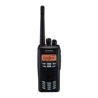
| Purpose | Digital Mobile Radio (DMR) |
|---|---|
| Maximum range | - m |
| Operating frequency | 136 - 174 MHz |
| Shockproof | Yes |
| Product color | Black |
| Compatible products | KNB57L, KSC25 |
| International Protection (IP) code | IP55 |
| Number of batteries supported | 1 |
| Operating temperature (T-T) | -20 - 60 °C |
| Display type | LCD |
| Depth | 39.5 mm |
|---|---|
| Width | 56 mm |
| Height | 110.5 mm |
| Weight | 330 g |






 Loading...