EasyManua.ls Logo

Kenwood NX-220 K User Manual

Kenwood NX-220 K
110 pages
To Next Page IconTo Next Page
Page #1 background imageLoading...
Page #1 background image
SERVICE MANUAL
This product uses Lead Free solder.
This product complies with the
RoHS
directive for the European market.
© 2011-3 PRINTED IN JA PAN
B51-8962-00
(
N
)
405
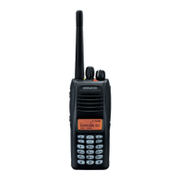
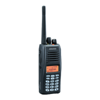
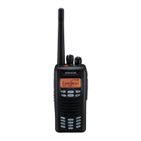
NX-220
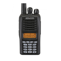
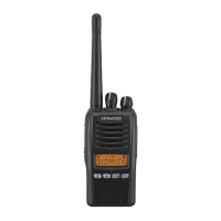
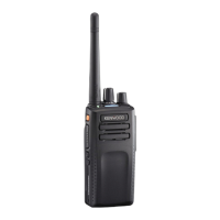
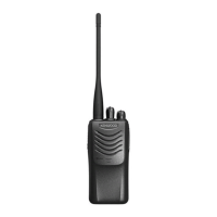
VHF DIGITAL TRANSCEIVER
Does not come with antenna.
Antenna is available as an option.
Knob (Volume)
(K29-9485-03)
Knob (Selector)
(K29-9486-03)
Knob (PTT)
(K29-9500-03)
Button knob
(Side1/Side2/AUX)
(K29-9501-03)
Plastic cabinet assy
(A02-4132-03)
Packing (4Key)
(G53-1864-01)
Packing (16Key)
(G53-1865-01)
Plastic cabinet assy
(A02-4131-03)
Plastic cabinet assy
(A02-4130-03)
Helical antenna
(KRA-22: Option)
Knob (Volume)
(K29-9485-03)
Knob (Selector)
(K29-9486-03)
Knob (PTT)
(K29-9500-03)
Button knob
(Side1/Side2/AUX)
(K29-9501-03)
Helical antenna
(KRA-22: Option)
Knob (Volume)
(K29-9485-03)
Knob (Selector)
(K29-9486-03)
Knob (PTT)
(K29-9500-03)
Button knob
(Side1/Side2/AUX)
(K29-9501-03)
Helical antenna
(KRA-22: Option)
NX-220 K,E3 NX-220 K2,E2 NX-220 K3,E
Question and Answer IconNeed help?

Do you have a question about the Kenwood NX-220 K and is the answer not in the manual?

Kenwood NX-220 K Specifications

General IconGeneral
BrandKenwood
ModelNX-220 K
CategoryTransceiver
LanguageEnglish

Summary

General Overview and Safety

Personal Safety Precautions

Details essential safety precautions to be observed during operation and servicing.

Realignment and Mode Operations

PC Mode and Firmware Programming

Details PC mode for programming, firmware updates, and connection procedures.

Disassembly and Repair Procedures

Circuit Description Overview

Receiver Path Circuits

Describes RF, IF, audio amplifier, squelch, and other receiver circuits.

Transmitter Path Circuits

Details VOX, amplifiers, APC, PLL synthesizer, and transmitter path circuits.

Parts List and Specifications

Troubleshooting Guide

Power Supply and Clock Checks

Details checks for power supply voltage and clock signals to diagnose issues.

PCB Replacement and ESN Management

Steps after PCB change: firmware update, data writing, adjustments, and ESN label layout.

Adjustment Procedures (K Type)

Frequency, Signaling, and Transmitter Adjustments

Details frequency, signaling, transmitter power, balance, and deviation adjustments.

Receiver Adjustments

Covers AF level, sensitivity, RSSI, and squelch adjustments for the receiver.

Test Equipment and Procedures

Lists alignment equipment, adapters, and radio check procedures.

Adjustment Procedures (E Type)

Frequency, Signaling, and Transmitter Adjustments (E Type)

Details E-type frequency, signaling, transmitter power, and deviation adjustments.

Receiver Adjustments (E Type)

Covers AF level, sensitivity, RSSI, and squelch adjustments for E-type receiver.

Test Equipment and Procedures (E Type)

Lists alignment equipment, adapters, and radio check procedures for E-type.

Terminal Functions

Specifications (K Type)

General Specifications (K Type)

Lists general model, frequency, channel, and dimension details for K Type.

Receiver Specifications (K Type)

Details receiver performance metrics like sensitivity and selectivity for K Type.

Transmitter Specifications (K Type)

Details transmitter performance metrics like power output and modulation for K Type.

Specifications (E Type)

Related product manuals