Do you have a question about the Kenwood TK-3000 K and is the answer not in the manual?
Overview of the service manual's scope and purpose.
Guide on how to order necessary replacement parts.
Essential safety precautions for handling the equipment.
General notes on servicing the transceiver.
Description of different operational modes like User, PC, Clone.
Procedures to access various operational modes.
Steps and descriptions for programming via PC.
Procedure for transferring data between transceivers.
Instructions for detaching the case from the chassis.
Steps to remove the TX-RX unit from the chassis.
Procedure for removing the rear panel of the unit.
Cautionary note on handling the speaker lead during disassembly.
Explanation of the transceiver's frequency tuning and configuration.
Description of the internal receiver block diagram and components.
Details on RF amplifier and first mixer circuits.
Explanation of the intermediate frequency amplifier stages.
Description of the audio signal processing path.
Description of the transmitter block diagram and components.
Details on the microphone signal amplification.
Explanation of RF power amplification stages.
Description of the PLL and VCO frequency generation.
Explanation of the microcontroller and its functions.
Description of encode and decode signaling functions.
Overview of the power supply circuits and voltage rails.
List of test equipment needed for alignment procedures.
Guidance on connecting antenna adapter and DC power supply.
Procedures for aligning frequencies and signaling parameters.
Initial setup steps and key adjustment points.
Alignment procedures for common and transmitter sections.
Alignment procedures for receiver sensitivity and squelch.
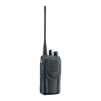
Basic operating parameters and physical characteristics.
Performance metrics for the receiver section.
Performance metrics for the transmitter section.
Basic operating parameters and physical characteristics.
Performance metrics for the receiver section.
Performance metrics for the transmitter section.
| Channels | 16 |
|---|---|
| Power Output | 5W |
| Dimensions | 54 x 113 x 24.9 mm |
| Operating Voltage | 7.5 V DC ±20% |
| Modulation | 16K0F3E / 11K0F3E |
| Frequency Range | 400-470 MHz |
| Battery Life | 10 hours |
| Channel Spacing | 12.5 kHz / 25 kHz |