EasyManua.ls Logo

Kenwood TK-3000 User Manual

Kenwood TK-3000
51 pages
To Next Page IconTo Next Page
Page #1 background imageLoading...
Page #1 background image
SERVICE MANUAL /
This product uses Lead Free solder.
This product complies with the RoHS directive for the European market.
UHF FM TRANSCEIVER / UHF
TK-3000
© 2011-5 PRINTED IN JAPAN
B51-8978-00
(
Y
)
Helical antenna
(T90-1098-05)
Button knob (Side)
(K29-9490-13)
Knob (PTT)
(K29-9489-13)
Knob (Volume)
(K29-9487-03)
Knob(Selector)
(K29-9488-03)
C6 version / C6
无铅焊接通信产品
保护环境建伍领先
注意∶
本产品是无铅化焊接产品
在维修时请使用无铅焊锡
和相应的焊接工具
详细事项请访问如下网址了解 :
http://www.kenwoodhk.com.hk/
版本
调频手持对讲机
维修手册
天线
按钮 (PTT)
钮(侧面)
机壳
旋钮(选择器)
旋钮(音量)
Plastic cabinet assy
(A02-4135-03)

Other manuals for Kenwood TK-3000

Question and Answer IconNeed help?

Do you have a question about the Kenwood TK-3000 and is the answer not in the manual?

Kenwood TK-3000 Specifications

General IconGeneral
Channel Capacity16 channels
Power Output5W
Operating Temperature Range-30°C to +60°C
Operating Voltage7.5V DC ±20%
Modulation16K0F3E/11K0F3E
Battery Life14 hours
Weight203 g
Channel Spacing25 kHz/12.5 kHz
Frequency Range400-430 MHz

Summary

GENERAL / 概述

PERSONAL SAFETY

Essential safety precautions for operating the equipment.

REALIGNMENT / 模式组合

3. PC Mode

Details on using the PC for programming and data transfer.

3-7. Programming with PC

Explains how to program the transceiver via PC.

DISASSEMBLY FOR REPAIR / 维修拆卸

1. Separating the Case Assembly from the Chassis

Step-by-step guide to separate the case assembly from the chassis.

2. Removing the TX-RX unit from the Chassis

Instructions for removing the TX-RX unit from the transceiver chassis.

3. Removing the Rear Panel

Steps to remove the rear panel of the transceiver.

CIRCUIT DESCRIPTION / 电路说明

3-2. Drive and Final Amplifier Circuit

Details the drive and final amplifier stages for RF output.

5. Control Circuit

Describes the MCU and its control functions for the TX-RX unit.

2. Receiver System

Overview of the receiver system, including RF amplifier and mixer stages.

4. Frequency Synthesizer Circuit

Explains the components and operation of the frequency synthesizer.

EXPLODED VIEW / 部件分解图

ADJUSTMENT

Transmitter Section

Adjustment procedures specific to the transmitter section.

ADJUSTMENT / 调整

1. Setting

Initial setup parameters and standard modulation settings.

1. Sensitivity Check

Procedure to check receiver sensitivity under narrow and wide band.

ADJUSTMENT

Receiver Section

Adjustment procedures for receiver sensitivity and squelch level.

PC BOARD / 印刷电路板

SCHEMATIC DIAGRAM / 原理图

TX-RX UNIT (X57-8100-23)

Detailed schematic of the TX-RX unit, showing component interconnections.

BLOCK DIAGRAM / 方块图

TX-RX UNIT (X57-8100-23)

Block diagram illustrating the functional modules of the TX-RX unit.

SPECIFICATIONS / 规格

General

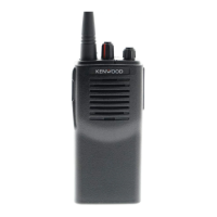
General specifications including frequency range, channels, and battery life.

Related product manuals