Do you have a question about the Kenwood TK-3201 and is the answer not in the manual?
Manual's purpose, intended for experienced technicians with commercial grade communications equipment.
Guidance on how to order replacement parts, including part identification numbers and chassis/kit numbers.
Precautions for personal safety, including RF connector verification and avoiding explosive atmospheres.
Information on servicing the radio, referencing diagrams, PC board views, and alignment procedures.
Describes User mode, PC mode, Data programming mode, and PC test mode for radio operation.
Explains how to enter User mode (Power ON) and PC mode (Received commands from PC).
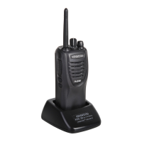
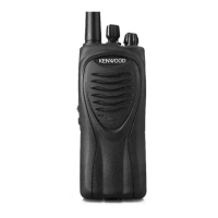
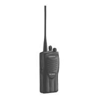
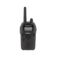
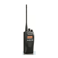
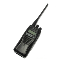
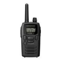
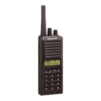
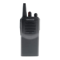
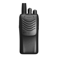
Identifies key physical components of the transceiver like Antenna, LED indicator, Channel selector, and PTT switch.
Details PC programming setup using KPG-22 cable and KPG-90D software with an IBM PC.
Steps to remove knobs, screws, and lift the chassis from the case assembly.
Steps to remove packing, screws, bracket, antenna/positive terminals, and FPC from TX-RX unit.
Instructions for re-attaching the battery release lever, mounting chassis, and assembly precautions.
Notes on knob nuts, screw sequence for TX-RX unit, and connecting speaker wires.
Details the receiver's double conversion system and PLL circuit for frequency generation.
Explains receiver front end, mixer, IF amplifier, audio amplification, squelch, and signalling.
Explains the PLL circuit for reception and transmission, including VCO operation and phase comparison.
Details the transmitter system, including microphone amplifier, drive/final amplifier, and APC circuit.
Covers unlock detector, encode signalling, power supply, and control circuits.
Explains the control system, including keys and channel selector inputs to the microprocessor.
Lists the pin functions for connector CN401, detailing each pin's name, I/O, and function.
Provides pin function details for the microprocessor (IC405).
Lists components used in the TX-RX unit, their reference numbers, functions, and operations.
Details capacitor coding for types, shapes, temperature coefficients, voltage ratings, values, and tolerances.
Explains resistor coding for types, wattage, value, and tolerance, including chip and normal types.
Lists parts for the TX-RX unit, including cabinets, chassis, knobs, levers, covers, and various hardware.
Lists chip capacitors (C47-C160) for the TX-RX unit, specifying type, value, and tolerance.
Lists further components for the TX-RX unit, including chip capacitors, inductors, and connectors.
Details resistors (R1-R323) for the TX-RX unit, specifying part numbers, description, and wattage.
Lists remaining resistors (R324-R455) and diodes (D1-D405) for the TX-RX unit.
Visual representation of the TK-3201 assembly with numbered parts for identification.
Illustrates the contents of the TK-3201 package, including accessories like charger, battery, and manual.
Lists necessary test equipment for radio alignment, such as SSG, power meter, and oscilloscope.
Specifies required parts like antenna connector adapters and repair jigs for performing adjustments.
Highlights key adjustment points on the TX-RX unit, including VR1 and CV terminals.
Provides pre-adjusted frequencies and signalling settings for the TK-3201.
Outlines pre-tuning steps, including power supply connection and dummy load usage.
Details adjustment procedures for common settings like VCO lock voltage and power.
Covers adjustments for frequency, power, VOX, deviation, and signalling parameters.
Explains adjustments for BPF wave check, sensitivity, and squelch levels.
Shows the component layout on the TX-RX unit's component side, with reference numbers.
Continues the component layout diagram for the TX-RX unit's component side.
Continues the component layout diagram for the TX-RX unit's component side.
Shows the component layout on the TX-RX unit's foil side, with reference numbers.
Displays the schematic diagram for the TX-RX unit, showing circuit connections and components.
Continues the schematic diagram for the TX-RX unit, detailing various circuit sections.
Continues the schematic diagram for the TX-RX unit, showing power supply and control circuits.
Continues the schematic diagram for the TX-RX unit, detailing RF amplifier and detection circuits.
Provides a block diagram illustrating the overall functional blocks of the TX-RX unit.
Continues the block diagram, showing the microprocessor and its interfaces.
Illustrates the signal levels in the receiver section from RF input to AF output.
Shows the signal levels in the transmitter section from microphone input to RF output.
Details specifications and external view of the KSC-31 rapid charger.
Provides specifications and external view for the KNB-29N Ni-MH battery pack.
Details specifications and external view for the KNB-30A Ni-Cd battery pack.
Shows the external view of the KBH-10 belt clip.
Covers frequency range, channels, operating voltage, battery life, and environmental conditions.
Details receiver performance metrics like sensitivity, selectivity, and intermodulation.
Covers transmitter performance metrics like RF power output, modulation, and audio distortion.
| frequency range | 446.0~446.1MHz |
|---|---|
| number of channels | 16 |
| channel spacing | 12.5kHz |
| PLL channel stepping | 12.5kHz |
| operating voltage | 7.5 V DC ±20% |
| frequency stability | ±2.5ppm (–30˚C to +60˚C) |
| channel frequency spread | 0.1MHz |
| battery life with KNB-29N battery (battery saver off) | Approx. 16 hours |
|---|---|
| battery life with KNB-29N battery (battery saver on) | Approx. 20 hours |
| battery life with KNB-30A battery (battery saver off) | Approx. 11 hours |
| battery life with KNB-30A battery (battery saver on) | Approx. 15 hours |
| battery life with KNB-45L battery (battery saver off) | Approx. 20 hours |
| battery life with KNB-45L battery (battery saver on) | Approx. 25 hours |
| operating temperature range | –30˚C to +60˚C (–22 ˚F to +140 ˚F) |
|---|
| sensitivity EIA 12dB SINAD | 0.28µV |
|---|---|
| sensitivity EN 20dB SINAD | -3dBµV (0.7µV) |
| selectivity | 60dB |
| intermodulation | 60dB |
| spurious response | 60dB |
| audio power output | 500mW at 8 Ω less than 10% distortion |
| RF power output | ERP 0.5W |
|---|---|
| spurious response | 65dB |
| modulation | 8K50F3E |
| FM noise | 40dB |
| audio distortion | Less than 5% |
| dimensions (radio only) | 54 W x 122 H x 21.1 D mm |
|---|---|
| weight (radio only) | 163g |
| dimensions with KNB-29N battery | 54 W x 122 H x 33 D mm |
| weight with KNB-29N battery | 363g |
| dimensions with KNB-30A battery | 54 W x 122 H x 33 D mm |
| weight with KNB-30A battery | 343g |
| dimensions with KNB-45L battery | 54 W x 122 H x 33 D mm |
| weight with KNB-45L battery | 283g |