NX-5000 Remote Configuration [Initial Setup Instruction]
Page | 3
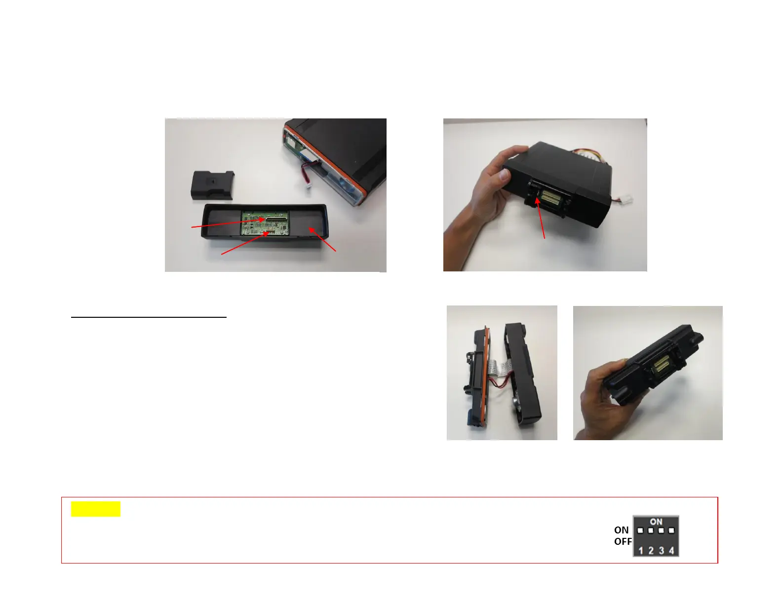
4) Insert the cable into the connector (CN2) of the KRK-15BM <Figure 3>.
5) Insert the flat cable into the connector (CN1) of the KRK-15BM. Note: Exercise care when inserting the flat cable into CN1.
6) Fit the KRK-15BM with four tabs onto the front of the chassis. Note: Per Figure 4, the dip switch shall be on the left side as shown.
KRK-14HM Assembly Instructions
KRK-14HM is required if the basic head, KCH-19RM is used.
It is not required for the full feature control head, KCH-20RM.
1) Insert the cable into the connector (CN2) of KCH-19M.
2) Insert the flat cable into the connector (CN6) of KCH-19M.
Note: Exercise care when inserting the flat cable into CN6.
Note: The position of the flat cable needs to be inserted properly so
the traces on the cable line up with the connector CN6.
3) Fit the four tabs of the KRK-14HM into the KCH-19M. Note: Apply limited pressure to lock in position.
CAUTION:
When writing firmware for the initial setup, verify that he DIP switches (1~4) mounted on each interface adapter
(KRK-14H, KRK-15B, and KCH-20R) are set to ON.
 Loading...