(No.RA018<Rev.002>)1-31
(6) Press the packing evenly to the base of the chassis.
Note:
To prevent doing any damage, do not press forcefully on
the packing.
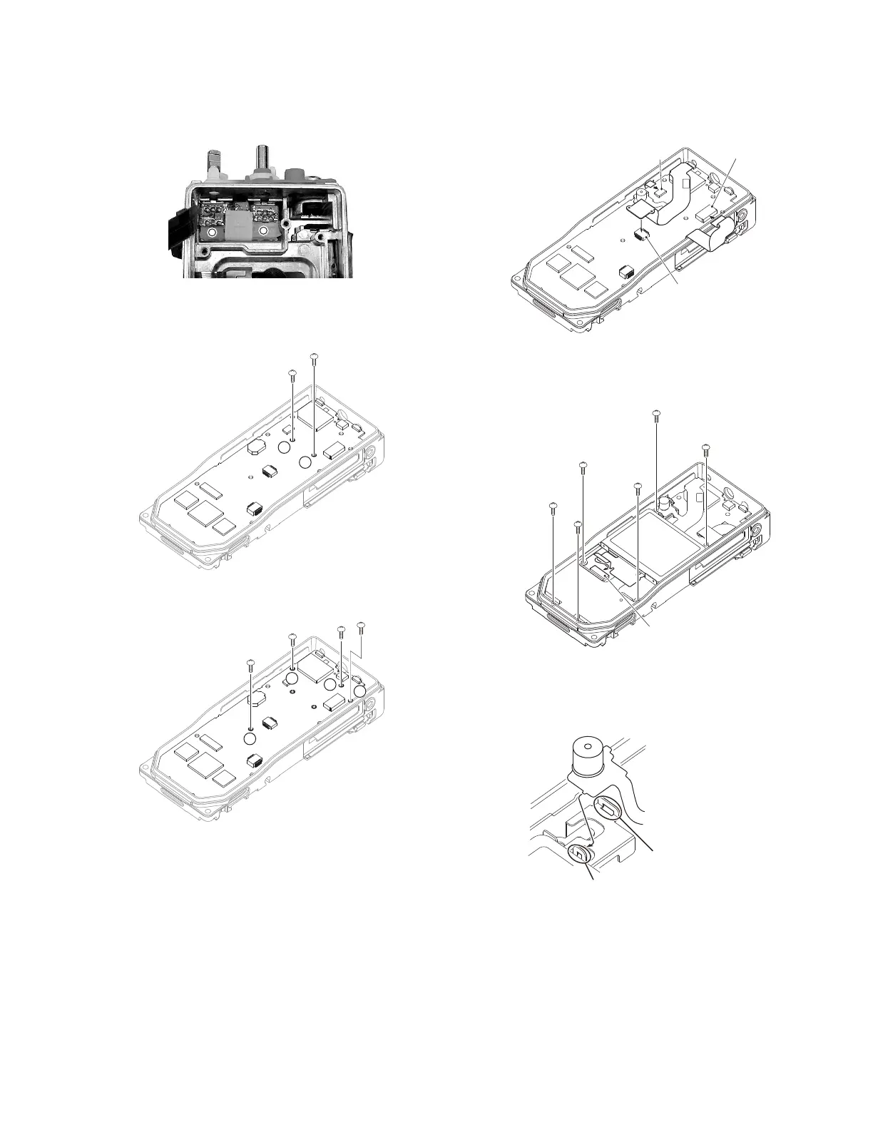
3.3.2 Install the main unit in the chassis
(1) Tighten the two screws (black) <1> to affix the battery ter-
minal block to the chassis.
(2) Tighten the four screws <2> to affix the main unit to the
chassis.
(3) Insert the universal connector FPC into the connector
(CN12). <3>
(4) Insert the PTT FPC into the connector (CN8). <4>
(5) Insert the VOL/SEL/MIC FPC into the connector (CN4).
<5>
(6) Place the LCD shield cover on the main unit and tighten the
six screws. <6>
(7) Insert the LCD FPC into the connector (CN9). <7>
(8) After inserting the hooks on the top side of the VOL/SEL/
MIC FPC (mic part) into the holes on the top side of the
LCD shield cover, insert the hooks on the bottom side of
the FPC into the holes on the bottom side of the shield cov-
er.
<3>
<4>
<5>
Connector(CN12)
Connector(CN4)
Connector(CN8)
<7>
<6>
<6>
<6>
<6>
<6>
<6>
Connector(CN9)
Hooks on top side of FPC
Hooks on bottom side of FPC
 Loading...