EasyManua.ls Logo

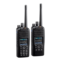
Kenwood NX-5200 K2 User Manual

Kenwood NX-5200 K2
126 pages
To Next Page IconTo Next Page
Page #1 background imageLoading...
Page #1 background image
SERVICE MANUAL
COPYRIGHT © 2015 JVC KENWOOD Corporation
No.RA018<Rev.002>
2015/9
B5B-7164-10
VHF DIGITAL TRANSCEIVER
RA018<Rev.002>20159SERVICE MANUALB5B-7164-10
NX-5200
COPYRIGHT © 2015 JVC KENWOOD Corporation
TABLE OF CONTENTS
1 PRECAUTION. . . . . . . . . . . . . . . . . . . . . . . . . . . . . . . . . . . . . . . . . . . . . . . . . . . . . . . . . . . . . . . . . . . . . . . . . 1-7
2 SPECIFIC SERVICE INSTRUCTIONS . . . . . . . . . . . . . . . . . . . . . . . . . . . . . . . . . . . . . . . . . . . . . . . . . . . . . . 1-7
3 DISASSEMBLY . . . . . . . . . . . . . . . . . . . . . . . . . . . . . . . . . . . . . . . . . . . . . . . . . . . . . . . . . . . . . . . . . . . . . . 1-27
4 ADJUSTMENT . . . . . . . . . . . . . . . . . . . . . . . . . . . . . . . . . . . . . . . . . . . . . . . . . . . . . . . . . . . . . . . . . . . . . . . 1-34
5 TROUBLESHOOTING . . . . . . . . . . . . . . . . . . . . . . . . . . . . . . . . . . . . . . . . . . . . . . . . . . . . . . . . . . . . . . . . . 1-94
NX-5200 F3,K3,ENX-5200 F2,K2,E2
This service manual has been revised due to the addition of NX-5200 type E, E2.
REVISED
This product complies with the RoHS directive for the European market.
This product uses Lead Free solder.

Table of Contents

Questions and Answers:

Kenwood NX-5200 K2 Specifications

General IconGeneral
Frequency Range136-174 MHz
Operating Temperature-30°C to +60°C
Operating Voltage7.5V DC ±20%
GPSOptional
Ingress ProtectionIP67
MIL-STDMIL-STD-810 C/D/E/F/G
Power Output5W
WaterproofYes
Channel Spacing12.5 kHz / 25 kHz
Digital ProtocolNXDN
Modulation16K0F3E, 11K0F3E

Summary

SECTION 2 SPECIFIC SERVICE INSTRUCTIONS

2.2 REALIGNMENT

2.2.3 Panel Test Mode

Details the features and access to the panel test mode for diagnostics.

2.2.4 Panel Tuning Mode

Explains how to access and use the panel tuning mode for adjustments.

2.2.6 Firmware Programming Mode

Covers the procedure for upgrading transceiver firmware via flash memory.

2.2.8 Front Panel Programming Mode

Details manual channel data setup and modification via the front panel.

2.3 INSTALLATION

2.4 CIRCUIT DESCRIPTION

SECTION 3 DISASSEMBLY

3.1 Precautions for Waterproof

Emphasizes crucial precautions to maintain transceiver waterproof integrity during disassembly.

3.2 Precautions for Disassembly

Highlights essential precautions to take before and during disassembly.

3.3 Precautions for Reassembly

SECTION 4 ADJUSTMENT

4.2 Panel Test Mode

Explains the features and key operations available in the panel test mode.

4.3 Panel Tuning Mode

Describes how to enter and operate the panel tuning mode.

4.3.1 Transceiver tuning (To enter tuning mode)

Provides instructions for entering the transceiver tuning mode.

4.4 BER (Bit Error Rate) Measurement

Outlines the procedure for measuring Bit Error Rate using a digital radio tester.

4.9 Transmitter Section

3. High transmit power (Battery voltage : 7.5V)

Covers adjustment of high transmit power based on battery voltage.

4. Medium transmit power (Battery voltage : 7.5V)

Details adjustment of medium transmit power based on battery voltage.

5. Low transmit power (Battery voltage : 7.5V)

Explains adjustment of low transmit power based on battery voltage.

7. Maximum Deviation *2

Covers adjustments for maximum deviation in various analog modes.

8. P25 High Deviation

Details adjustments for P25 high deviation.

9. P25 H-CPM Deviation

Covers adjustments for P25 H-CPM deviation.

10. NXDN High Deviation

Explains adjustments for NXDN high deviation.

11. QT Deviation *3

Details adjustments for QT deviation in different analog modes.

12. DQT Deviation *3

Covers adjustments for DQT deviation in different analog modes.

13. LTR Deviation *3

Details adjustments for LTR deviation in different analog modes.

14. DTMF Deviation *3

Explains adjustments for DTMF deviation in different analog modes.

15. Single Tone Deviation *3

Covers adjustments for single tone deviation in different analog modes.

16. MSK Deviation *3

Details adjustments for MSK deviation in different analog modes.

17. CWID Deviation *3

Explains adjustments for CWID deviation in analog narrow mode.

18. Battery Warning Level writing

Covers the procedure for writing battery warning level values.

20. Internal Microphone Gain

Details the adjustment of internal microphone gain, exclusively in PC test mode.

4.10 Receiver Section

2. Sensitivity 1

Details the adjustment procedure for receiver sensitivity 1 across various points.

3. Sensitivity 2

Explains the adjustment process for receiver sensitivity 2, aiming for a specific SINAD level.

5. Open Squelch

Details squelch level adjustments for various modes (Analog, P25, NXDN).

8. Tight Squelch

Details the procedure for adjusting tight squelch levels in various analog modes.

4.11 E, E2 TYPE Controls

4.11.2 Panel Test Mode

Explains features and key operations in the Panel Test Mode for E/E2 types.

4.13 Panel Tuning Mode

4.13.1 Transceiver tuning (To enter tuning mode)

Provides instructions for entering the transceiver tuning mode.

2. Receive Assist

Details automatic and manual adjustments for receiver assist.

3. Transmit Assist

Explains automatic and manual adjustments for transmitter assist.

4. Frequency

Covers frequency adjustment procedures, emphasizing PC test mode.

SECTION 5 TROUBLESHOOTING

5.4 Replacing Main Unit

Related product manuals