Do you have a question about the Kenwood R-599 and is the answer not in the manual?
Lists the various frequency bands the R-599 receiver can tune.
Details receiver sensitivity and selectivity for different modes and bands.
Outlines frequency stability and image ratio performance.
Specifies power requirements, consumption, dimensions, and weight.
Instructions for unpacking and inspecting the receiver.
Guidance on selecting a place for installation and connecting power, antenna, and speaker.
How to connect the R-599 receiver with a T-599 transmitter or other transmitters.
Details on installing crystals for spot frequency reception.
Procedures for installing 50 MHz and 144 MHz converters.
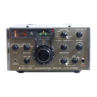
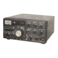
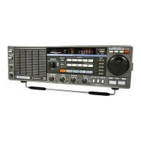
Detailed explanation of all controls on the front panel of the R-599 receiver.
How to read the frequency displayed on the receiver's dials.
Steps to calibrate the frequency indicating dial for accuracy.
Description of controls and connectors on the rear panel of the R-599 receiver.
Initial settings required before operating the R-599 receiver.
Overview of the R-599 receiver's capabilities and operating principles.
Explanation of the RF attenuator, peak limiting, and RF amplifier stages.
Details on the intermediate frequency stages, filters, AGC, and squelch circuits.
Description of filters used for different modes (SSB, CW, AM, FM).
Explanation of the Variable Frequency Oscillator (VFO) and RIT circuit.
Details on the Beat Frequency Oscillator (BFO) for carrier generation.
How the marker unit generates 25 kHz and 100 kHz signals.
Explanation of the voltage regulator circuit providing stable power.
Instructions for removing the receiver's cabinet and bottom plate.
Maintenance procedure for the VFO drive gears.
Information on replacing pilot lamps.
Procedure for adjusting the marker oscillator.
Steps for adjusting the AVR unit's voltage output.
Adjustment procedure for the AF unit's output amplifier.
How to adjust the monitor circuit output level.
Adjustment procedure for the sidetone circuit in CW operation.