EasyManua.ls Logo

Kenwood R-2000 Service Manual

Kenwood R-2000
32 pages
To Next Page IconTo Next Page
Page #1 background imageLoading...
Page #1 background image
$KEN\NOOD
SERVICE
MJ\NUl\L
R-2000
DCK-1
COMMUNICATIONS
RECEIVER
CONTENTS
SPECIFICATIONS
........................................................... 2
DISASSEMBLY .............................................................
22
CIRCUIT
DESCRIPTION
.................................................. 3
PACKING
..........................
...........................................
23
PARTS
LIST
..................................................................
11
ADJUSTMENT
.............................................................
24
PC
BOARD
VIEW
AND
SCHEMATIC
DIAGRAM
ADJUSTMENT POINT ..................................................
29
RX
UNIT (X55-1340-00)
.......................................
16
TERMINAL FUNCTION
.................................................
30
PLL
UNIT (X50-1920-00)
......................................
18
BLOCK DIAGRAM ........................................................
31
SWITCH UNIT (X41-1480-00) .............................
20
DCK-1
(OPTION)
........................................
BACK
COVER
SCHEMATIC
DIAGRAM ...............................................
21

Other manuals for Kenwood R-2000

Question and Answer IconNeed help?

Do you have a question about the Kenwood R-2000 and is the answer not in the manual?

Kenwood R-2000 Specifications

General IconGeneral
Tuning Range150 kHz - 30 MHz
Sensitivity (SSB, CW)0.5 µV
Signal to Noise Ratio (MW)50 dB
Signal to Noise Ratio (LW)50 dB
Distortion (FM)0.5%
Frequency response (FM)30 Hz - 15 kHz
Power SupplyAC 120/220 V, 50/60 Hz
Sensitivity (FM)1.0 µV
Selectivity (SSB, CW)2.4 kHz (-6 dB)
OutputSpeaker, Line out
ModeAM, FM, SSB

Summary

SPECIFICATIONS

CIRCUIT DESCRIPTION

RX Unit X55-1340-00

Detailed description of the R-2000's receiver unit circuitry and operation.

PLL Unit X50-1920-00

Explanation of the Phase Locked Loop unit's circuit and functions, including frequency synthesis.

PC BOARD VIEW

Unit Component Layouts

Component layouts for RX, PLL, Encoder, and Switch units showing PCB placement.

SCHEMATIC DIAGRAM

DISASSEMBLY

ADJUSTMENT

PLL and Encoder Adjustments

Steps for adjusting PLL section, VCO, encoder, and PG SCAN speed.

Receiver Adjustments

Procedures for adjusting receiver parameters like sensitivity, S meter, and squelch.
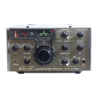
ADJUSTMENT POINT

BLOCK DIAGRAM

Related product manuals