R-2000
CIRCUIT
DESCRIPTION
RX
unit
X55-1340-00
R-2000
is a
triple
conversion
general
coverage receiver with
a first
IF
of
45.85
,....,
45.90
MHz.
9.85
,....,
9.90
MHz second
IF
and a
455
kHz
third
IF.
Both
low
(50.Q)
or high
(500.Q)
impedance antenna termin-
als
are provided for
all
bands.
The
signal supplied
through the antenna
terminal
goes to
the antenna fuse
(100
mA)
and three step
RF
attenuator
(10, 20, and
30
dB).
It next enters the
BPF
(Band
Pass
Filter).
which divides the
0.15
,..,
30
MHz range into 6
bands;
0.15
MHz
,....,
1
MHz.
1 MHz
,_,
2 MHz, 2 MHz
,..,
4
MHz. 4 MHz
,....
8 MHz. 8
MHz
,....
17 MHz and 17
MHz.,_,
30
MHz.
058:
SN74LS145N
converts the
BCD
band data
signal
from the
PLL
control circuit to
select
the appropriate
BPF
for the frequency
selected.
Exiting the
BPF.
the signal,
is
fed to
RF
amp
01
:
3SK73(GR).
first
IF
trap {operating at
40.875
MHz) and
emitter
follower
02:
2SC
181 5
(Y).
The
RF
signal
is
mixed with the first
local oscillator
45.9
,....,
75.85
MHz and converted to the
45.85
,_,
45.90
MHz first
IF
by
balanced
mixer
03
and
04:
3SK73(GR).
03
and
04
drain voltage
is
supplied through a switching cir-
cuit consisting of
05
and
06
controlled
by
04
7 and
048
:
2SC1815
(Y)
will
turn off when the
VHB
signal
is
applied
from the
PLL
control
circuit
in
the (optional)
VHF
reception
mode.
At
the same time, the first
IF
circuit input
is
switched
to the converter
by
switching diodes D 13 and D 14:
1
S2588.
After passing the first
IF
LC
filter
the signal
is
converted to
the 9.85
,....,
9.90
MHz second
IF
by
the second
balanced
mixer
07
and
08:
3SK74(L)
using the
36
MHz second local
oscillator
injection
signal.
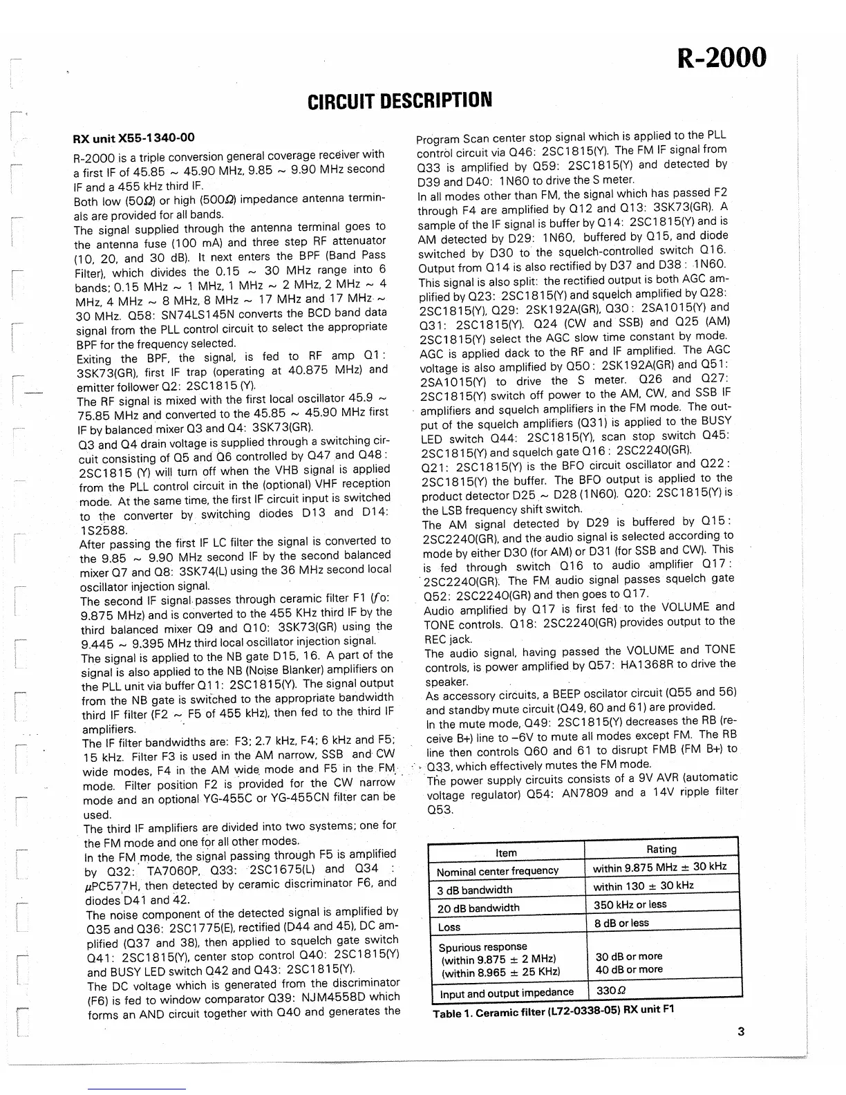
The second
IF
signal.
passes through ceramic
filter
F1
(fo:
9.875
MHz) and
is
converted to the
455
KHz
third
IF
by the
third
balanced mixer
09
and
010:
3SK73(GR) using the
9.445
,...,
9.395
MHz third
local oscillator
injection
signal.
The signal
is
applied
to the
NB
gate D 1
5,
1
6.
A part of the
signal
is
also applied
to the
NB
(Noi.se
Blanker) amplifiers
on
the
PLL
unit
via
buffer
011:
2SC
1815(Y). The
signal
output
from the
NB
gate
is
switched
to the appropriate bandwidth
third
IF
filter
(F2
"".
F5
of
455
kHz).
then fed to the third
IF
amplifiers.
·
The
IF
filter
bandwidths
are:
F3; 2.7
kHz.
F4; 6
kHz
and
F5;
1 5
kHz.
Filter
F3
is
used
in
the AM narrow,
SSB
and-
CW
wide modes. F4
in
the AM
wide.
mode and
F5
in
the
FM·
mode.
Filter
position
F2
is
.provided for the
CW
narrow'
·
mode and
an
optional YG-455C
or YG-455CN
filter
can
be
used .
. The third
IF
amplifiers
~re
divided into
two
systems;
one
for
the FM mode and
one
for
all
other modes.
In
the FM. mode, the signal passing through
F5
is
amplified
by
032:
TA7060P, 03·3: 2SC1675(L)
and
034
:
µPC57.7H.
then detected
by
ceramic discriminator
F6,
and
diodes.D41 and
42.
The noise component of the detected signal
is
amplified
by
035
and
036:
2SC1775(E).
rectified (D44 and 45),
DC
am-
plified
(037
and 38). then
applied to squelch gate switch
04
1 :
2SC
1
81
5(Y).
center stop
control
040:
2SC
1
81
5(Y)
and
BUSY
LED
switch
042
and
043:
2SC1815(Y).
The
DC
voltage
which
is
generated from the discriminator
(F6)
is
fed to window comparator
039:
NJM4558D
which
forms an AND circuit together with
040
and generates the
Program
Scan
center stop
signal
which
is
applied
to the
PLL
control circuit
via
046:
2SC
1815(Y).
The
FM
IF
signal
from
033
is
amplified by
05
9:
2SC
1
81
5(Y)
and detected
by
D39 and
D40:
1
N60
to drive the
S
meter.
In
all
modes other than
FM.
the signal which
has
passed
F2
through F4
are
amplified
by
012
and
013:
3SK73(GR). A
sample
of the
IF
signal
is
buffer
by
014:
2SC
1815(Y) and
is
AM detected
by
D29: 1
N60.
buffered
by
015,
and diode
switched
by
D30
to the squelch-controlled
switch
0 1
6.
Output from
014
is
also
rectified
by
D37
and
D38:
1
N60.
This
signal
is
also split:
the rectified output
is
both
AGC
am-
plified
by
023:
2SC
1
81
5(Y)
and squeich
amplified
by
028:
2SC1815(Y).
029:
2SK192A(GR),
030:
2SA1015(Y)
and
031:
2SC1815(Y).
024
(CW
and
SSB)
and
025
(AM)
2SC
1
81
5(Y)
select
the
AGC
slow
time constant by mode.
AGC
is
applied dack to the
RF
and
IF
amplified.
The
AGC
voltage
is
also amplified
by
050
:
2SK 192A(GR) and
051
:
2SA1015(Y)
to drive the
S
meter.
026
and
027:
2SC
1815(Y) switch off power to the AM.
CW.
and
SSB
IF
·
amplifiers and squelch amplifiers
in
the
FM
mode.
The
out-
put of the
squelch amplifiers
(031)
is
applied
to the
BUSY
LED
switch
044:
2SC
1
81
5(Y).
scan stop switch
045:
2SC
181
5(Y)
and squelch gate
01
6 :
2SC2240(GR).
021
:
2SC
1
81
5(Y)
is
the
BFO
circuit oscillator
and
022
:
2SC
181
5(Y)
the buffer.
The
BFO
output
is
applied to the
product detector
D25
,...,
D28
{ 1
N60).
020:
2SC
181
5(Y)
is
the
LSB
frequency shift switch.
The
AM signal detected
by
D29
is
buffered
by
015:
2SC2240(GR).
and the audio signal
is
selected according to
mode
by
either
D30
(for AM) or
D31
(for
SSB
and
CW).
This
is
fed through switch
016
to audio amplifier
01
7 :
· 2SC2240(GR).
The
FM
audio signal passes
squelch gate
052:
2SC2240(GR)
and then goes to
017.
Audio
amplified
by
017
is
first
fed· to the
VOLUME
and
TONE
controls.
018:
2SC2240(GR)
provides output to the
REC
jack.
The
audio
signal.
having passed the
VOLUME
and
TONE
controls.
is
power
amplified
by
05
7: HA 1 368R to drive the
speaker.
As
accessory circuits, a
BEEP
oscilator circuit
(055
and 56)
and standby mute circuit
(049.
60
and 61)
are
provided.
In
the mute mode.
049:
2SC1815(Y)
decreases the
RB
(re-
ceive
B+)
line
to
-6V
to mute
all
modes except
FM.
The
RB
line then controls
060
and
61
to disrupt
FMB
(FM
B+)
to
:·
•
033.
which effectively mutes the
FM
mode.
The
power
supply
circuits consists of a 9V
AVR
(automatic
voltage
regulator)
054:
AN7809
and
a 14V
ripple filter
053.
Item
Rating
Nominal center frequency
within 9.875
MHz±
30
kHz
3 dB bandwidth
within
130
±
30
kHz
20
dB bandwidth
350
kHz
or less
Loss
8 dB or less
Spurious response
(within 9.875
±
2 MHz)
30
dB
or
more
(within 8.965
±
25
KHz)
40dBormore
Input
and output impedance
330.Q
Table
1. Ceramic filter
(L72-0338-05) RX unit
F1
3
 Loading...