Do you have a question about the Kenwood RD-DV7-L and is the answer not in the manual?
Introduction to test modes, including setup, cancellation, and general operation principles.
Guidance on handling the optical pickup, static precautions, and reassembly.
Detailed steps for adjusting the optical pickup's tilt for optimal performance.
Specific operations and displays for DVD and MD test modes.
Steps for preparing the MD mechanism for adjustment procedures.
Procedures for factory and sub clock oscillation diagnosis within test modes.
Steps to enter specific test modes, including disc loading and mode selection.
Detailed steps for performing auto pre-adjustment and auto adjustment modes.
Procedures for AUTO FAB adjustment and RESULT sub/final adjustment modes.
Steps for manual auxiliary adjustment, covering low reflection and high reflection discs.
Procedures for TEST-PLAY, TEST-REC, and EJECT modes.
Error codes generated by the self-check mode for circuit diagnostics.
| Tuner Bands | FM/AM |
|---|---|
| Remote Control | Yes |
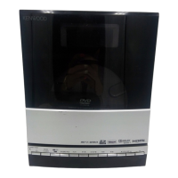
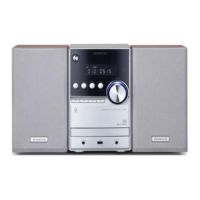
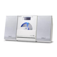
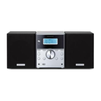
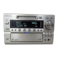
| Type | Mini Hi-Fi System |
| Functions | CD Player, Radio Tuner |
| Playable Media | CD-R, CD-RW |
| Video Output | Composite Video |