Do you have a question about the Kenwood RD-M515 and is the answer not in the manual?
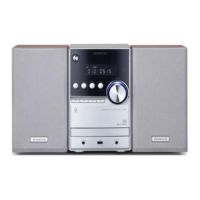
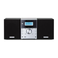
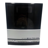
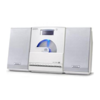
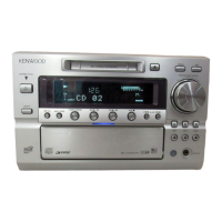
Identifies key buttons, knobs, and connectors on the front panel.
Crucial safety notice regarding the laser beam during repair or operation.
Lists the remote control unit and FM antenna supplied with the system.
Describes the procedure to enable and disable the dealer lock feature.
Warnings about electric shock, user-serviceable parts, and dangerous voltages.
Declaration of Conformity with EMC Directive and RoHS directive.
Instructions for proper disposal of electrical equipment and batteries.
Precautions for power cord, installation, operation, and general usage.
Specific warnings and guidelines related to the Class 1 laser product.
Schematic illustrating the Switch Mode Power Supply board layout and components.
Detailed circuit diagram of the main control board.
Schematic of the front panel control and interface circuitry.
Diagram illustrating the CD and MP3 processing circuitry.
Circuit diagram for the FM tuner section of the system.
Visual representation of the main unit's general assembly.
Comprehensive list of major physical components with part numbers.
Detailed lists of electrical components for various PCBs.
Details on power source, consumption, audio output/input, and tuner characteristics.
Information on speaker type, power handling capacity, and impedance.
| power source European models | AC 230 V, 50 Hz |
|---|---|
| power source Australian models | AC 240 V, 50 Hz |
| power consumption operation | 22 W |
| power consumption standby mode | 1 W or less |
| analog sound output speakers | 2 |
|---|---|
| output power | 20 W + 20 W at 6 Ω (10% THD) |
| fitting impedance | 6 Ω− 16 Ω |
| audio in normal | 500 mV/47 kΩ |
|---|---|
| audio in high | 250 mV/47 kΩ |
| iPod output power | DC 5 V 500 mA |
| FM tuner receiving frequency | 87.50 MHz to 108.00 MHz |
|---|---|
| antenna type | 75 Ω - unbalanced type |
| speaker power handling capacity | 20 W |
| main unit dimensions | 165 mm × 250 mm × 229 mm |
|---|---|
| main unit weight | 2.3 kg |
| speaker dimensions | 140 mm × 250 mm × 135 mm |
| speaker weight | 1.3 kg |