EasyManua.ls Logo

Kenwood RXD-A3 User Manual

Kenwood RXD-A3
37 pages
To Next Page IconTo Next Page
Page #1 background imageLoading...
Page #1 background image
MINI HiFi COMPONENT SYSTEM
RXD-251/301/301E/301W/
RXD-351/351E/351W/371S/A3
SERVICE MANUAL
© 1998-7/B51-5454-00 (K/K) 3763
(XD-251~A3)**
In compliance with Federal Regulations, following are reproduc-
tions of labels on, or inside the product relating to laser product
safety.
**Refer to page 2 if you want to know system configuration.
KENWOOD-Crop. certifies this equipment conforms to DHHS
Regulations No. 21 DFR 1040. 10, Chapter 1, Subchapter J.
DANGER : Laser radiation when open and interlock defeated.
AVOID DIRECT EXPOSURE TO BEAM
Panel(CD) *
(A60-)
Front glass *
(A29-)
Knob *
(K29-)
Knob
(K29-7512-08)
Knob
(K29-7519-08)
Knob
(K29-7518-08)
Phone jack
(E11-0386-08)
Konb
(K-29-7516-08)
Cassette lid(R) *
(A53-)
Front glass(R)
(B10-3451-08)
Front panel *
(A60-)
Knob *
(k29-)
Knob
(K29-7523-08)
Knob
(K29-7522-08)
Knob
(K29-7521-08)
Cassette lid(L) *
(A53-)
Front glass(L)
(B10-3450-08)
Knob
(K29-7515-08)
Knob
(K29-7511-08)
Mic jack
(E11-0387-08)
Knob *
(K29-)
Knob *
(K29-)
Knob
(K29-7513-08)
Illust. is RXD-351.
* Refer to parts list on page 38.
Question and Answer IconNeed help?

Do you have a question about the Kenwood RXD-A3 and is the answer not in the manual?

Kenwood RXD-A3 Specifications

General IconGeneral
BrandKenwood
ModelRXD-A3
CategoryStereo System
LanguageEnglish

Summary

External View of the Component System

Unit Connectivity and Ports

Illustrates external connections like antenna, AUX, speakers, and power.

Controls Overview

Front Panel and Disc Controls

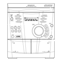
Describes the operation of front panel buttons for disc management.

Receiver Unit Operational Controls

Details buttons, knobs, and terminals for receiver functions.

Sound Mode Selection

Explains the various sound quality settings available.

Controls - Continued

Cassette Deck Operation

Covers controls for the cassette playback and recording functions.

Display Indicators and Functions

Describes the information shown on the unit's display and related indicators.

Block Diagram of System Interconnections

System Unit Interconnections

Visual representation of how different system units are connected.

Circuit Description

Microprocessor Pin Description

Details the function of each pin on the main microprocessor.

Circuit Description - Continued

Control Matrix and I/O Extension

Explains the function of control buttons and port extension interfaces.

LCD Light On Mode

Describes a special mode for illuminating the LCD screen.

CD Mechanism Operation Description

Disc 3 Insertion and Detection

Explains how disc 3 is loaded and detected by the mechanism.

Tray Open/Close Operation

Describes the process of opening and closing the disc tray.

CD Mechanism Operation Description - Continued

Pickup Replacement Procedure

Step-by-step guide for replacing the CD pickup assembly.

Adjustment Procedures

FM Section Tuning Adjustments

Procedures for fine-tuning FM reception parameters.

MW Section Tuning Adjustments

Steps for adjusting Medium Wave radio tuning.

SW Section Tuning Adjustments

Procedures for adjusting Short Wave radio tuning.

Adjustment Procedures - Continued

Radio Tuning Instruments Connection

Diagrams showing how to connect test instruments for radio adjustments.

Adjustment Procedures - Further Details

Cassette Deck Section Adjustments

Procedures for calibrating the cassette deck.

PC Board Adjustment Procedures

Details adjustments made on the printed circuit boards.

Adjustment Procedures - Advanced

Laser Power and Bias Adjustment

Steps for adjusting laser power and focus error bias for CD playback.

Wiring Diagram

System Unit Wiring Connections

Illustrates the electrical connections between all system units.

Parts Descriptions

Component Identification and Values

Explains how to identify capacitors and resistors by their markings.

PC Board Component Side View

Tuner Unit PC Board Layouts

Shows the component placement for different tuner unit configurations.

PC Board Component Side View - Continued

RXD-371S Tuner Unit PC Board

Details the component layout for the RXD-371S tuner board.

PC Board Component Side View - Audio Unit

Audio Unit PC Board Layout

Illustrates the component arrangement on the audio unit board.

PC Board Component Side View - Display Unit

Display Unit PC Board Layout

Shows the component placement for the unit's display board.

Exploded View of the Unit

Unit Component Assembly Diagram

Visual guide showing how the unit's parts are assembled.

Parts List

Reading the Parts List Conventions

Explains how to interpret the information in the parts list.

Model and Destination Codes

Lists abbreviations for models and their country of destination codes.

Specifications

Main Unit Power and Circuit Specs

Details amplifier power output and circuit specifications.

Cassette and CD Player Specifications

Lists technical details for cassette and CD playback functions.

Speaker System Specifications

Provides dimensions, impedance, and type for speaker systems.

Tuner Section Frequency Ranges

Outlines the tuning frequency ranges for various regions.

Related product manuals