EasyManua.ls Logo

Kenwood RXD-A33 User Manual

Kenwood RXD-A33
36 pages
To Next Page IconTo Next Page
Page #1 background imageLoading...
Page #1 background image
70%
MINI HiFi COMPONENT SYSTEM
RXD-303/303E/353/353E/503/503E/553/553E/
SERVICE MANUAL
(XD-303~A73)**
© 2000-3/B51-5605-00 (K/K) 3633
DISC
1
DISC
2
DISC
3
STANDBY
TIMER
DISPLAY/DEMO
MENU
SELECTBACK ENTER
SOUND
CONTROL
TUNING
MODE
M
U
L
T
I
C
O
N
T
R
O
L
REC/ARM
REVERSE
MODE
TAPE EQ.
PHONES
DISC SKIP
OPEN/
CLOSE
E
X
.
B
A
S
S
PUSH
OPEN
PUSH
OPEN
DECK
PLAY
A
DECK
REC/PLAY
B
VOLUME
CONTROL
Panel ass'y *
(A60-)
Knob *
(K29-)
Panel(CD) *
(A29-)
Front glass *
(B10-)
Knob *
(K29-)
Phone jack
(E11-0280-05)
553-GR/553E-GR/653/653E/A33/A53/A53-GR
* Refer to parts list on page 33.
In compliance with Federal Regulations, following are repro-
ductions of labels on, or inside the product relating to laser
product safety.
**Refer to page 2 if you want to know system configuration.
KENWOOD-Crop. certifies this equipment conforms to DHHS
Regulations No. 21 DFR 1040. 10, Chapter 1, Subchapter J.
DANGER : Laser radiation when open and interlock defeated.
AVOID DIRECT EXPOSURE TO BEAM
Question and Answer IconNeed help?

Do you have a question about the Kenwood RXD-A33 and is the answer not in the manual?

Kenwood RXD-A33 Specifications

General IconGeneral
CD PlayerYes
TunerFM/AM
Cassette DeckYes
Frequency Response20 Hz - 20 kHz
FunctionsCD Player, Cassette Deck
Output Power30W per channel (RMS)
Speaker Impedance6 Ohms
CD SectionCompatible with CD-R/CD-RW
TypeStereo Receiver

Summary

System Identification and Front Panel

Product Model and Service Manual Title

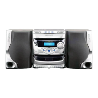
Identifies the product model and the service manual itself.

Front Panel Component Layout

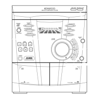
Diagram illustrating the location of controls, jacks, and indicators on the front.

Safety and Compliance Information

Important warnings regarding laser safety and regulatory compliance.

Accessories, Configuration, and Initialization

Included System Accessories

List of accessories provided with the main unit.

System Configuration by Model

Table detailing model variations and associated speaker configurations.

Microcomputer Reset Procedure

Step-by-step guide to reset the system's microcomputer.

External Views and Disassembly

Rear and Side Panel Identification

Diagram identifying connectors and ports on the rear and sides.

Tray Opening Procedure for Repair

Instructions on how to open the CD tray for servicing.

System Block Diagram

Functional Block Interconnections

High-level diagram showing the interconnection of major system functional blocks.

Circuit Description and System Operation

Initial Setup and System Initialization

Procedures for setting up the system and initializing its default conditions.

System Test Modes and Diagnostics

Detailed procedures for entering and operating various system test modes.

Microprocessor Functions and Pinouts

Explanation of the microprocessor's role and detailed pin assignment descriptions.

Adjustment Procedures

Idle Current and Laser Adjustment

Steps for adjusting amplifier idle current and CD laser output.

Cassette Deck and Board Adjustments

Procedures for adjusting cassette tape speed, playback level, and bias current.

System Wiring Diagrams

Destination-Specific Wiring Schematics

Wiring diagrams illustrating connections for different regional models.

Component Identification and Specifications

Capacitor and Resistor Coding

Guide to interpreting markings and codes for capacitors and resistors.

Chip Component Dimensions and Ratings

Information on physical size and electrical ratings for chip components.

Printed Circuit Board Component Layouts

PC Board X32-3800-10 Component View

Diagram showing component placement on the X32-3800-10 board.

PC Board X13-7710-10 Component View

Diagram showing component placement on the X13-7710-10 board.

PC Boards X14 and X28 Component Views

Diagrams showing component placement on X14 and X28 boards.

Exploded Views

Mechanism Exploded View

Diagram illustrating the assembly of the cassette mechanism.

Exploded Views (Continued)

Unit Exploded View

Diagram illustrating the assembly of the main unit.

Parts List

Component Listings and Model Variations

Comprehensive list of parts, categorized by model and type.

How to Read the Parts List

Guide on interpreting part numbers, descriptions, and destination codes.

Specifications

Amplifier and Cassette Deck Specifications

Technical performance data for amplifier and cassette deck sections.

CD Player and General Specifications

Technical performance data for CD player and overall system features.

Related product manuals