Do you have a question about the Kenwood RXD-DV50 and is the answer not in the manual?
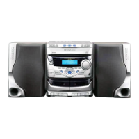
| Functions | CD, DVD, Tuner |
|---|---|
| CD Player | Yes |
| DVD Player | Yes |
| Tuner | FM/AM |
| Remote Control | Yes |
| Frequency Response | 20Hz - 20kHz |
| Speakers | 2 speakers included |
| Power Output | 50W per channel |
| Total Harmonic Distortion | 0.1% |
| Inputs | AUX |
| Outputs | Headphone |
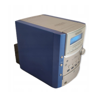
| Type | Stereo System |
Calibration steps for tape deck and amplifier settings.
Component layouts for Standby-Video, Sensor, and Control circuit boards.
Circuit diagrams for the main board and microphone amplifier section.
Circuit diagrams for the power amplifier board.
Circuit diagrams for the standby-video board.