EasyManua.ls Logo

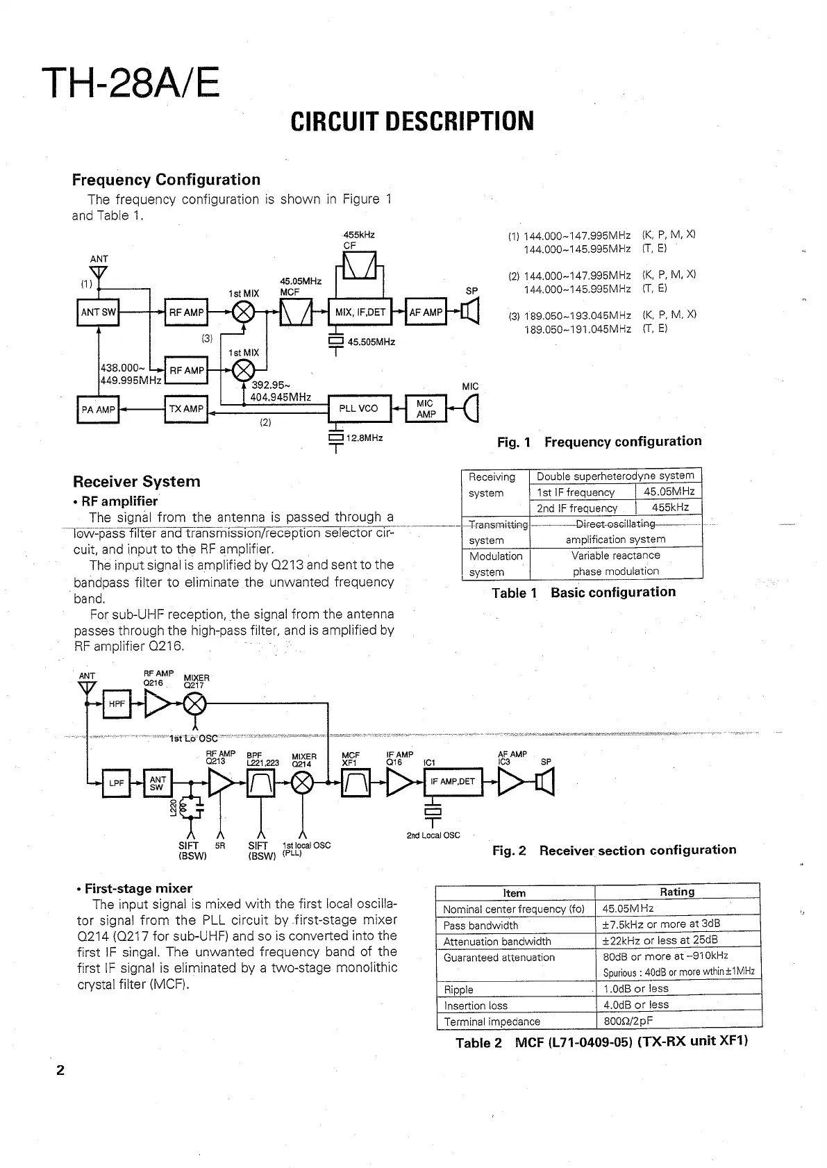
Kenwood TH-28E - CIRCUIT DESCRIPTION; Frequency Configuration; Receiver System

Kenwood TH-28E
66 pages
Print Icon
To Next Page IconTo Next Page
To Previous Page IconTo Previous Page
Loading...
TH-28A/E
CIRCUIT
DESCRIPTION
Frequency
Configuration
The
frequency
configuration
is
shown
in
Figure
14
and
Table
1.
455kH2
(1)
144.000~147.995MHz
{K,
P,
M,
x)
CF
144,000~145.995MHz_
(T,
&)
ANT
/
ma
45.05MHz
(2)
144,000~147.995MHz_
{K,
P,
M,
X)
tstMIX
MCE
SP
444,000~145.995MHz
(T,
&)
ANTSW
RE
AMP
py
MIX.
IF.DET
[mj
AF
AMP
(3)
189.050~193.045MHz
_
{K,
P,
M.
X)
—_
189.050~191.045MHz
(T,
E)
C3
45.505MHz
ist
MIX
“T
438.000~
Left
RE
AMP
449.995MHz
392.95
~
MIC
404.945MHz
MIG
PA
AMP
TX
AMP
.
PLLVCO
ey
ANP
(|
(2)
a
=
12.6MHz
Fig.
1
Frequency
configuration
Receiver
System
Receiving
Double
superheterodyne
system
-
RE
amplifier
system
1st
IF
frequency
45.05MHz
ee
.
2nd
IF
f
ne
455kHz
The
signal
from
the
antenna
is
passed
through
a
=
.
reqveny
1
—-
-
.
Transmitting|—-——-Direct-osceillating—————-—--|---
low-pass
filter
and
transmission/reception.
selector
cir-
system
amplification
system
cuit,
and
input
to
the
RF
amplifier.
“odulation
Variable
reactance
The
input
signal
is
amplified
by
Q213
and
sent-to
the
.
;
system
phase
modulation
bandpass
filter
to
eliminate
the
unwanted
frequency
=
-
_
band.
Table
1
Basic
configuration
For
sub-UHF
reception,
the
signal
from
the
antenna
passes
through
the
high-pass
filter,
and
is
amplified
by
RF
amplifier
Q216.
;
Ss
7
ee
pet
HPF
re)
of
assem
ma
nee
OL
ay
OG
Cement
sr]
seusemsminionsseniectenne
saints
penngeeg
=
gyn
bee]
LPF
be]
ANT
[
\
DH>-
IF
AMP,DET
41
&
—L
S
CI
|
=
2nd
Local
OSC
BSW)
on
BSW)
(sug
OS
Fig.2
Receiver
section
configuration
°
First-stage
mixer
.
item
Rating
The
input
signal
is
mixed
with
the
first
local
oscilla-
Nominal
center
frequency
(fo)
|
45.05MHz
tor
signal
from
the
PLL
circuit
by
first-stage
mixer
Pass
bandwidth
+7
5kHz2
of
more
at
3dB
0214
(Q217
for
sub-UHF)
and
so
is
converted
into
the
Attenuation
bandwidth
¥29kHz
or
less
at
2508
first
IF
singal.
The
unwanted
frequency
band
of
the
Guaranteed
attenuation
80dB
or
more
at
—910kHz
first
IF
signal
is
eliminated
by
a
two-stage
monolithic
Spurious
:
40¢B
or
more
wthin
+1MHz
crystal
filter
(MCF).
Ripple
|
1.0dB
or
less
Insertion
loss
4.0dB
or
less
Terminal
impedance
8000/2pF
Table
2.
MCF
(L71-0409-05)
(TX-RX
unit
XF1)