SERVICE MANUAL
This product uses Lead Free solder.
This product complies with the
RoHS
directive for the European market.
© 2010-11 PRINTED IN JA PAN
B51-8944-00
(
N
)
277
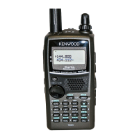
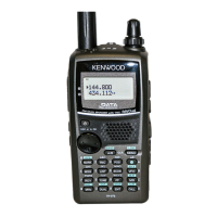
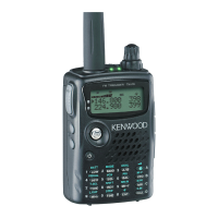
TH-D72A/D72E
144/440 (430) MHz FM DUAL BANDER
Whip antenna
(T90-1087-05)
Knob (PTT)
(K29-9457-03)
Button knob
(MONI/LAMP)
(K29-9460-03)
Button knob (Cross)
(K29-9464-03)
Packing (Chassis)
(G53-1843-11)
Knob (Volume)
(K29-9458-03)
Knob (Encoder)
(K29-9459-13)
Cap (SP/MIC)
(B09-0736-03)
Plastic cabinet assy
(A02-4092-13)
Front glass
(B10-2797-12)
CONTENTS
DISASSEMBLY FOR REPAIR ......................2
CIRCUIT DESCRIPTION ..............................4
SEMICONDUCTOR DATA .........................12
COMPONENTS DESCRIPTION .................16
TERMINAL FUNCTION .............................18
PARTS LIST ...............................................20
EXPLODED VIEW ......................................35
PACKING ....................................................36
TROUBLE SHOOTING ..............................37
ADJUSTMENT ..........................................39
PC BOARD
TX-RX UNIT (X57-784X-XX) (A,B/3) ....56
TX-RX UNIT (X57-784X-XX) (C/3) ........60
INTERCONNECTION DIAGRAM ..............64
SCHEMATIC DIAGRAM ............................66
BLOCK DIAGRAM .....................................82
LEVEL DIAGRAM ......................................84
OPTIONAL ACCESSORIES
BT-15 (Battery Case) .............................86
PB-45L (Li-ion Battery Pack) .................86
SPECIFICATIONS ......................................87