TH-K2AT/K2E/K2ET
2
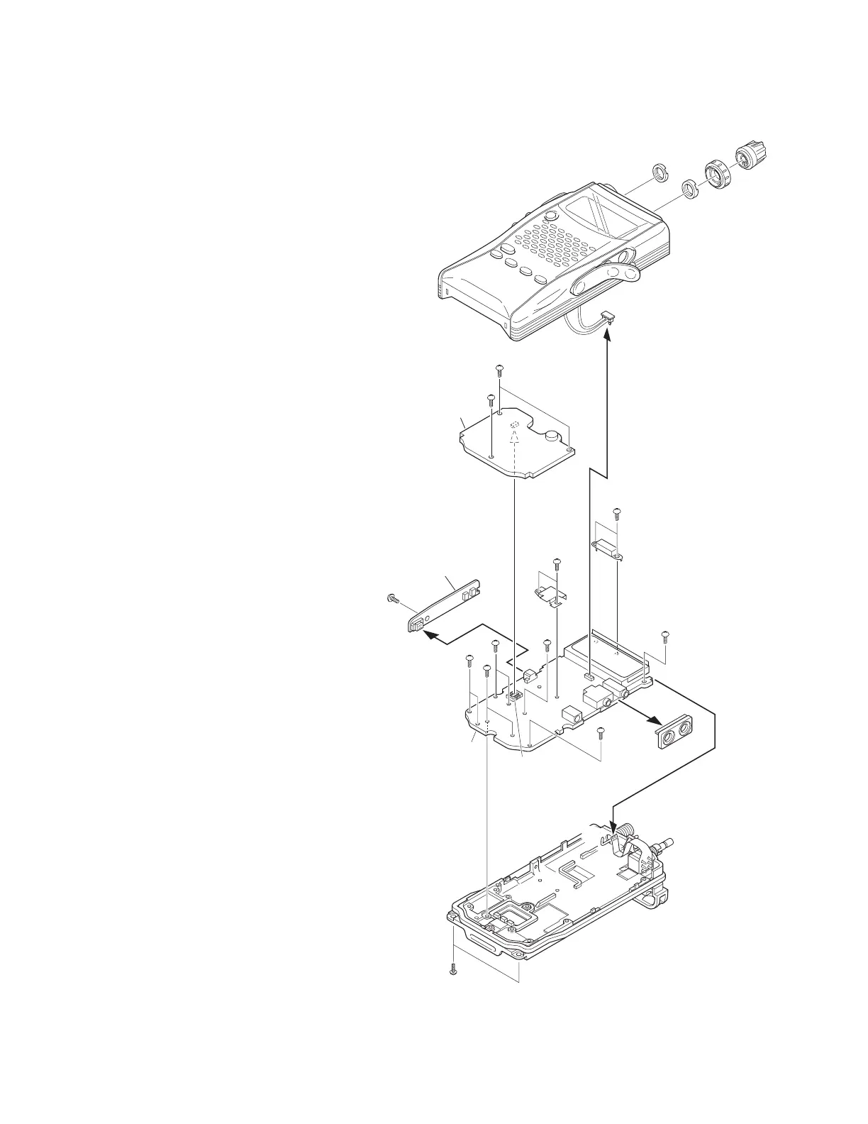
DISASSEM BLY FOR REPAIR
How to remove the case assembly from the
chassis
1. Remove tw o screw s (
z
) holding the chassis.
2. Pull out tw o knobs (
x
) and remove tw o round nuts (
c
).
3. Pull out the SP and M IC parts of the cap from jacks (
v
).
4. Turn the unit over w ith the bottom of the chassis facing
upw ards, and remove the chassis (
n
) from the case
assembly (
b
).
5. Remove the speaker lead (
m
) from the connector (CN2) of
the TX-RX PC board (TX-RX unit A/3).
How to remove the PC board
■ Numeric key PC board (TX-RX unit B/ 3)
1. Remove three screw s (
,
) on the numeric key PC board.
2. Lift the numeric key PC board and remove it from the
connector (CN9) of the TX-RX PC board (
.
).
■ PTT PC board (TX-RX unit C/ 3)
3. Remove one screw on the PTT PC board (
/
).
4. Pull the PTT PC board to the left and remove it from the
connector (CN6) of the TX-RX PC board (TX-RX unit A/3)
(
Ω
).
■ TX-RX PC board (TX-RX unit A/ 3)
5. Remove the SP/MIC jack cover (
≈
).
6. Remove tw o screw s (
ç
) holding the shield
cover (antenna terminal section).
7. Remove tw o screw s (
√
) holding the shield
cover (final amplifier section).
8. Remove eight screw s (
∫
) on the TX-RX PC
board.
9. Absorb solder from the antenna terminal (
~
)
w ith a solder absorber.
Note: Do not melt the shadow plate (
µ
) w hen
moving the tip of the solder absorber close
to the antenna terminal.
10. Remove the TX-RX PC board from the chassis, then remove
the encoder volume FPC (
≤
) from the flat cable connector
of the TX-RX PC board.
CN2
CN9
CN6
x
x
c
c
v
m
b
,
,
.
ç
√
µ
∫
∫
∫
∫
∫
Ω
/
∫
≈
~
≤
n
z
TX-RX unit (B/3)
TX-RX unit (C/3)
TX-RX unit (A/3)
 Loading...