EasyManua.ls Logo

Kenwood TK-2206 User Manual

Kenwood TK-2206
43 pages
To Next Page IconTo Next Page
Page #1 background imageLoading...
Page #1 background image
VHF FM TRANSCEIVER
TK-2202/2206
© 2004-2 PRINTED IN JAPAN
B51-8677-00 (S) 1246
SERVICE MANUAL
GENERAL .............................................................2
SYSTEM SET-UP .................................................2
REALIGNMENT....................................................3
DISASSEMBLY FOR REPAIR ..............................5
CIRCUIT DESCRIPTION .......................................8
TERMINAL FUNCTION......................................12
SEMICONDUCTOR DATA .................................12
COMPONENTS DESCRIPTION .........................13
PARTS LIST........................................................14
EXPLODED VIEW...............................................20
PACKING ............................................................21
ADJUSTMENT ...................................................23
PC BOARD
TX-RX UNIT (X57-6870-20)..........................28
SCHEMATIC DIAGRAM.....................................32
BLOCK DIAGRAM..............................................36
LEVEL DIAGRAM...............................................38
KSC-31 / KNB-29N / KNB-30A / KBH-10 .........39
SPECIFICATIONS............................BACK COVER
CONTENTS
Antenna
(T90-1036-05): TK-2202(K,M)
(KRA-26: Option) TK-2206 (M)
Knob (VOLUME)
(K29-9309-03)
Knob (PTT)
(K29-9308-03)
Cabinet assy
(A02-3852-23)(8CH):
TK-2202(K,M)
(A02-3851-23)(16CH):
TK-2206(M)
Knob (CH-SELECTOR)
(K29-9318-03)
TK-2206 :
Does not come with antenna.
Antenna is available as an option.
Photo is TK-2202.
Question and Answer IconNeed help?

Do you have a question about the Kenwood TK-2206 and is the answer not in the manual?
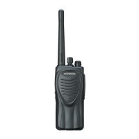
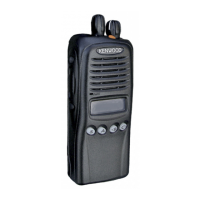
Kenwood TK-2206 Specifications

General IconGeneral
Frequency Range136-174 MHz
Channel Capacity16 Channels
Power Output5 W
Weight280 g (with KNB-29N)
Channel Spacing12.5/25 kHz
Modulation16K0F3E / 11K0F3E
Battery TypeLi-ion
Battery Capacity1500 mAh

Summary

GENERAL / SYSTEM SET-UP

INTRODUCTION

Manual intended for experienced technicians; contains service information.

ORDERING REPLACEMENT PARTS

Procedure for ordering replacement parts, including full part identification.

PERSONAL SAFETY

Precautions for personal safety during operation and servicing.

SERVICE

Information on ease of servicing and referring to diagrams.

SYSTEM SET-UP

REALIGNMENT

1. Modes

Describes the different operational modes (User, PC, Clone, Data programming, PC test).

2. How to Enter Each Mode

Details how to enter each operational mode (User, PC, Clone).

3. PC Mode

Explains PC mode setup, connection, and programming software.

4. Clone Mode

Explains the process of copying transceiver data to another unit.

DISASSEMBLY FOR REPAIR

Case Assembly Procedures

Steps for removing and attaching the case assembly.

Battery Release Lever Procedures

Steps for removing and attaching the battery release lever.

TX-RX Unit Removal and Attachment

Steps to detach and reattach the TX-RX unit.

Assembly Cautions and Receptacle Attachment

Assembly precautions, positive terminal, and antenna receptacle attachment.

Knob Nuts Handling

Information on volume and channel knob nuts and their removal.

CIRCUIT DESCRIPTION

Receiver and RF Configuration

Covers frequency config, receiver front-end, mixer, IF amp, and W/N switching.

Audio and Squelch Circuits

Details audio amplifier, squelch, and receive signalling circuits.

PLL and Transmitter Systems

Explains PLL, VCO, transmitter system, and microphone amplifier.

Power Supply and Control Circuits

Covers power supplies, control circuits, memory, and battery warning.

TERMINAL FUNCTION

SEMICONDUCTOR DATA

Microprocessor IC405 Details

Pin function details for the microprocessor IC405.

COMPONENTS DESCRIPTION

TX-RX UNIT (X57-6870-20) Components

Detailed description of components within the TX-RX unit.

Additional PCB Components

Description of components on the additional PCB.

PARTS LIST

TX-RX UNIT (X57-6870-20) - Main List

List of parts for the TK-2202/2206 TX-RX unit.

TX-RX UNIT (X57-6870-20) - Continued

Continuation of the parts list for the TX-RX unit.

EXPLODED VIEW

PACKING FOR TK-2202

PACKING FOR TK-2206

ADJUSTMENT

Test Equipment and Parts

Lists required test equipment and parts for alignment.

TX-RX Unit Adjustment Points

Highlights adjustment points on component and foil sides of the TX-RX unit.

Tuning Preparations and Common Settings

Covers tuning prep, frequency adjustments, and common settings.

Transmitter and Receiver Specific Adjustments

Details specific transmitter and receiver adjustments.

PC BOARD LAYOUTS

TX-RX Unit Component Side View

Diagram of the TX-RX unit component side with component placement.

Additional PCB Component Side View

Diagram of the additional PCB with component placement.

TX-RX Unit Foil Side View

Diagram of the TX-RX unit foil side with component placement.

SCHEMATIC DIAGRAM

BLOCK DIAGRAM

LEVEL DIAGRAM

ACCESSORIES

KSC-31 (Rapid Charger)

Details of the KSC-31 rapid charger.

KNB-29N (Ni-MH Battery Pack)

Specifications and schematic for KNB-29N battery.

KNB-30A (Ni-Cd Battery Pack)

Specifications and schematic for KNB-30A battery.

KBH-10 (Belt Clip)

External view of the KBH-10 belt clip.

SPECIFICATIONS

General Specifications

Covers frequency range, channels, voltage, and battery life.

Receiver Performance Specifications

Details receiver sensitivity, selectivity, and audio output.

Transmitter Performance Specifications

Details transmitter power, modulation, and noise.

Related product manuals